Axial Flow Turbo Machines
Product Details:
X
Product Description
AXIAL-FLOW TURBO MACHINES
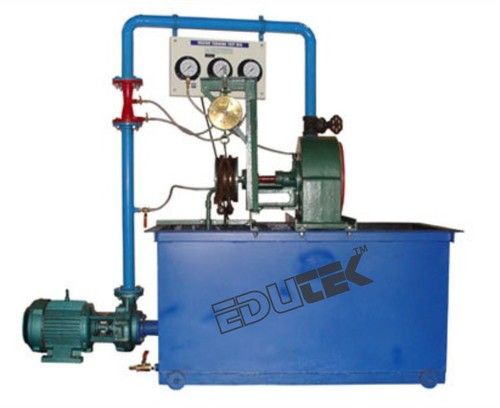
The core piece of the experimental plant is the axial turbomachine with attached asynchronous motor. It can be operated either as a pump or turbine. To this end, different rotors /impellers and stators / guide vane systems are used. Included in the scope of delivery are four rotors / impellers and four stators / guide vane systems supplied with different blade / vane angles. The experimental plant contains a closed water circuit with expansion tank and centrifugal pump. The compressed-air powered expansion tank allows the turbomachine to be converted without loss of water.The asynchronous motor functions during turbine operation as a generator, and during pump operation as a drive. A powerful pump generates flow and pressure during turbine operation. The power that is generated by the turbine is fed into this pump.
The speed is detected contact-free by means of an inductive displacement sensor on the motor shaft. To determine the drive power, the asynchronous motor is mounted on swivel bearings and equipped with a force sensor to measure the drive torque. Manometers measure the pressures at inlet and outlet. Pressure sensors measure the differential pressures at rotor / impeller and stator / guide vane system. The flow rate is measured by an electromagnetic flow meter. The measured values are read from digital displays.
The well-structured instructional material sets out the fundamentals and provides a step-by-step guide through the experiments.
- The unit shall perform the following experiments and investigations:
- Learning Objectives [Experiments
- Recording characteristic curves
- Determining dimension less characteristics
- Velocity triangles and pressure curves
- Investigation of energy conversion within the turbomachine
- How blade / vane shape affects power and efficiency
- Determining the outlet angular momentum and its effect on the power
- Cavitation effects
Specification:
- Investigation of an axial flow turbomachine
- Closed water circuit with expansion tank and centrifugal pump
- Turbomachine may be operated as a turbine and as a pump
- Two sets of impellers and guide vane systems for pump mode and two sets of rotors and stators for turbine mode with different inlet and outlet angles
- Asynchronous motor with 4-quadrant Operation via frequency converter
- Recovery of the brake energy
- Motor with pendulum bearing, torque measurement via lever arm and force sensor
- Inductive speed sensor on the motor
- Manometers for measuring the inlet and outlet pressures
- Measuring probe and differential pressure sensor for recording the pressure curve in the turbomachine
- Electromagnetic flow meter
- Display of power consumption, torque, speed, pressure, differential pressure and flow rate
- Technical Data
- Centrifugal pump
- Power: 5,5kW
- Max. flow rate: 150m3/h
- Max. head: 10m
- Asynchronous motor
- Power: 1,5kW
- Torque: ...5Nm
- Speed: 0...3000min-1
- Expansion tank: 1501_
- Measuring ranges
- Pressure (manometer): 2x -1...5bar
- Differential pressure: 5x 0...500Mbar
- Flow rate: 0...100m3/h
- Speed: 0...3000min-1
- Torque: 0...9,81Nrn
- Dimensions and Weight
- LxWxI-1: 3350 x 850 x 2465mrn
- Weight: approx..570kg
Tell us about your requirement

Price:
Quantity
Select Unit
- 50
- 100
- 200
- 250
- 500
- 1000+
Additional detail
+91
Email
Other Products in 'Fluid Mechanics Lab Equipment' category
"We deal all over World but our main domestic market is South India"
 |
EDUTEK INSTRUMENTATION
All Rights Reserved.(Terms of Use) Developed and Managed by Infocom Network Private Limited. |


