


Engineering Testing EquipmentPresenting our innovative Engineering Testing Equipment, which includes top-of-the-line products such as the CAR ENGINE ANALYZER, DIGITAL HIGH DISCHARGE BATTERY TESTERS, CROSSHOLE SEISMIC EQUIPMENT, Analogue Hydrostatic Pressure Testing Equipment, and Inclined Plane Tester. Our company, with over 51 years of experience, is a leading exporter, manufacturer, distributor, and supplier of these must-have tools for any engineering testing application. Our Engineering Testing Equipment has a supply ability in the domestic market throughout All India and is also exported to Africa. Our Engineering Testing Equipment offers five superb advantages and features, including perfect accuracy, gorgeous design, high durability, easy operation, and reliable performance. Whether you are testing engines, batteries, or structures, our products are specially designed to meet your needs and exceed your expectations. With our Engineering Testing Equipment, you can be sure that your testing results are accurate, reliable, and consistent. |
 (EDT-4623)
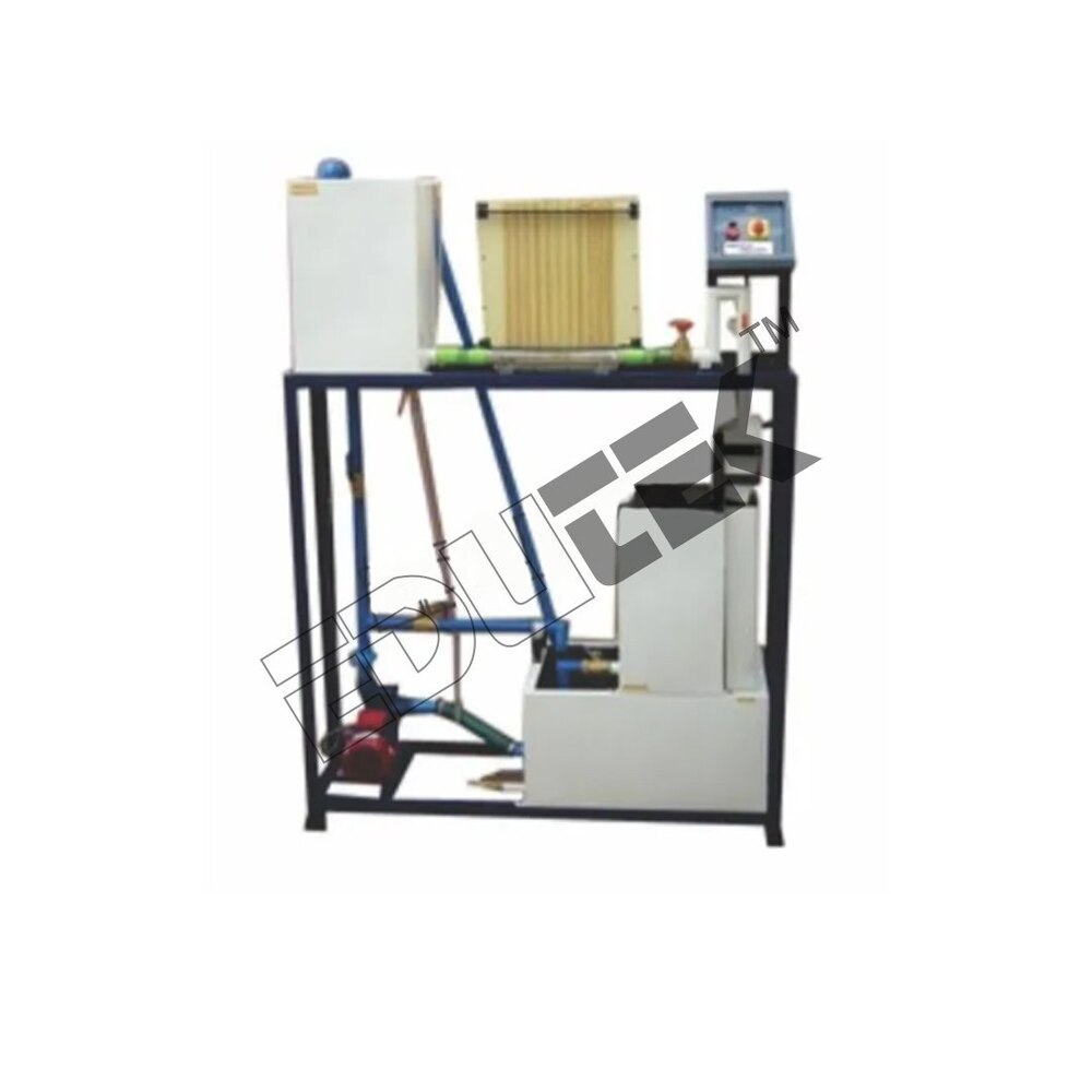
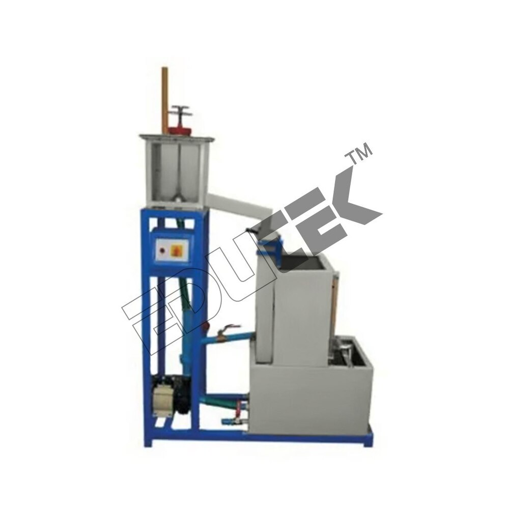
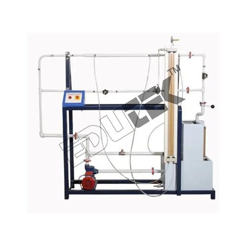
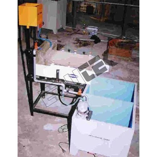
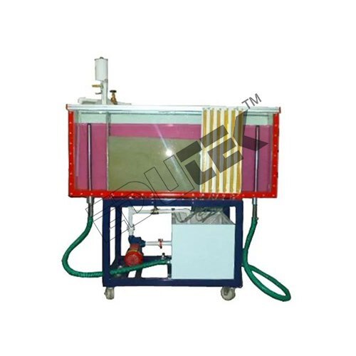
BERNOULLIS THEOREM APPARATUS.
Price: 500 INR/Piece
Specification: BERNOULLIS THEOREM APPARATUS Our organization is counted among the listed manufacturers, wholesalers and exporters of premium quality Bernoullis apparatus. Offered apparatus is precisely manufactured under strict supervision in compliance with industry laid parameters. These units consist of a rectangular transparent flow section through which water is to be flown. The velocity of water changes across the sectional area of channel changes. Experiments: To verify Bernoullis Theorem experimentally Utilities Required: Electric supply 0.5 kW, 220V AC, Single Phase Water supply Tap water connection BSP Distilled water 60 liters (optional) Floor Area with Drain facility Technical Specifications: Electric supply: 0.5 kW, 220V AC, Single Phase Inlet Tank Capacity: 20 Ltrs. MOC SS Supply Tank Capacity: 85 Ltrs. MOC SS Measuring Tank Capacity: 40 Ltrs. MOC SS fitted with Piezometer Tube & scale Piezometer Tubes: Material P.U. Tubes (9 Nos.)
 (ET-542S)
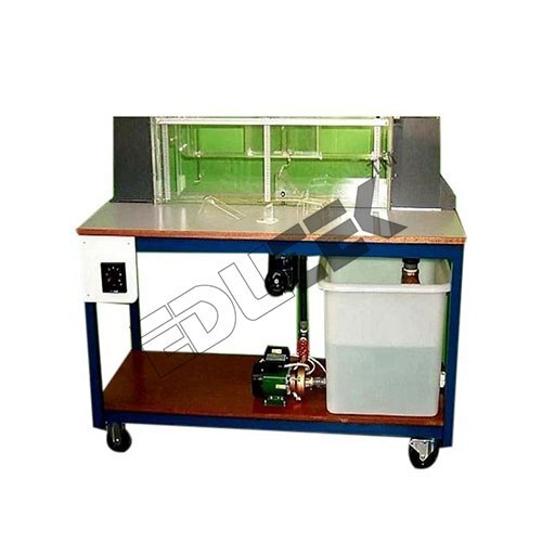
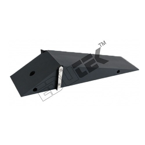
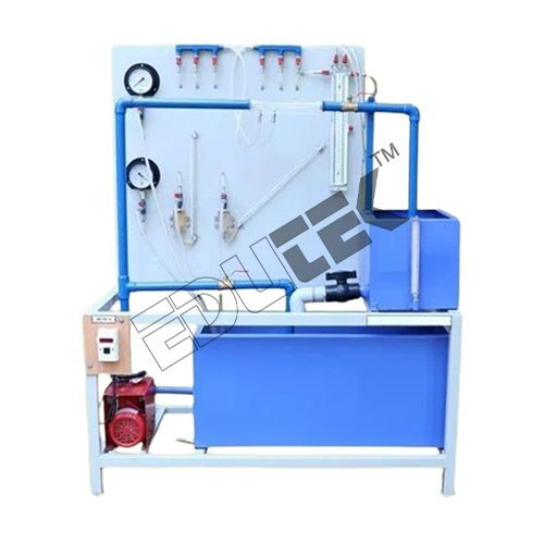
RECTANGULAR OVERSHOT WEIR/ BOARD CRESTED WEIR
Price: 500 INR/Piece
Specification: RECTANGULAR OVERSHOT WEIR/ BOARD CRESTED WEIR We have marked a remarkable position in the market by offering the best quality array of Broad Crested Weir. Features: Elevated durability Dimensional accuracy Easy usage
 (ETNA-51)
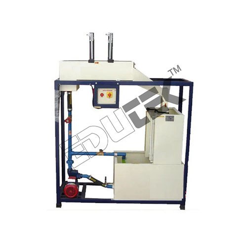
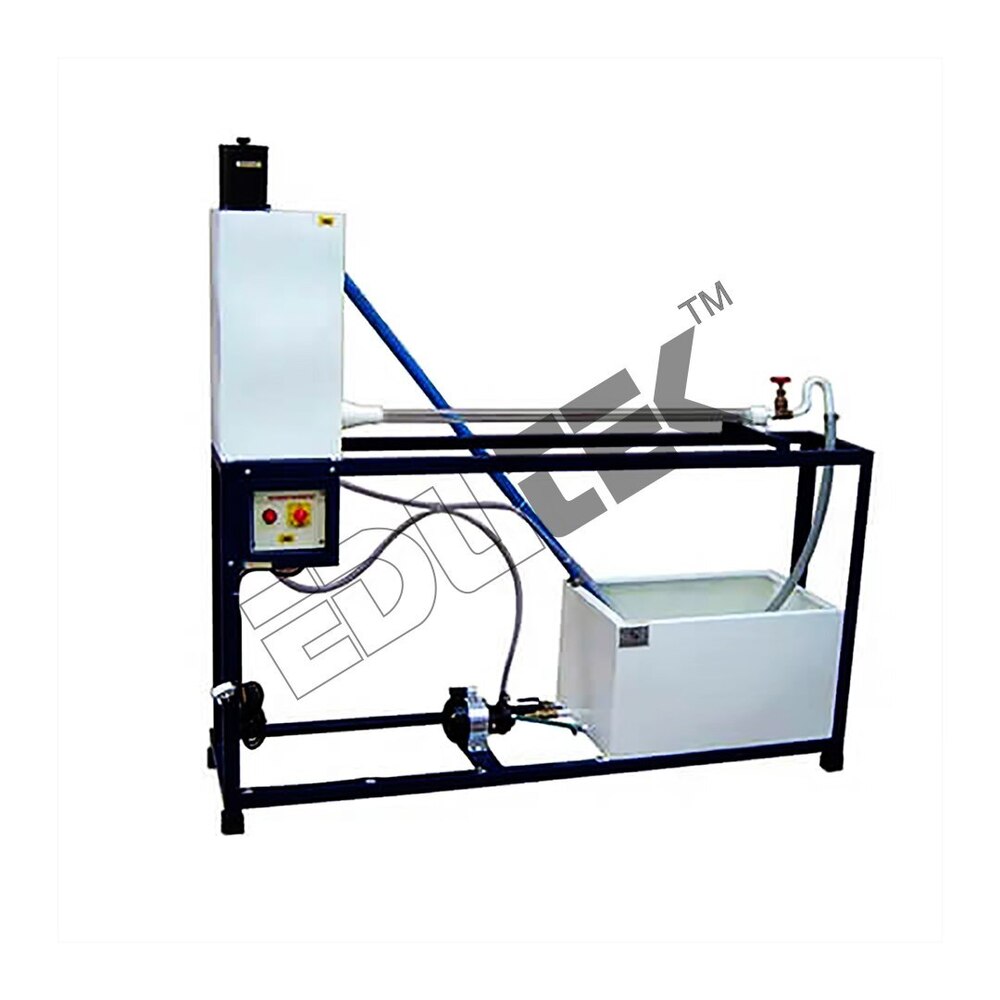
FLOW OVEN NOTCHES
Price: 500 INR/Piece
Specification: FLOW OVEN NOTCHES Offered by us are high-quality Flow over Notch to the esteemed customers, as per their specific requirements. These products are used for the purpose of testing and demonstrating the industrial machinery, thus, are highly demanded in the market. Our range of Flow over Notches is used to read and calculate the flow of water in metric units. Product Details: High-quality materials used Highly stable Extremely durable Reliable results Hassle-free flow of water all over the setup Robust shape
 (ET-907X)
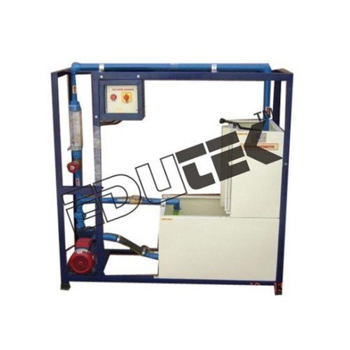
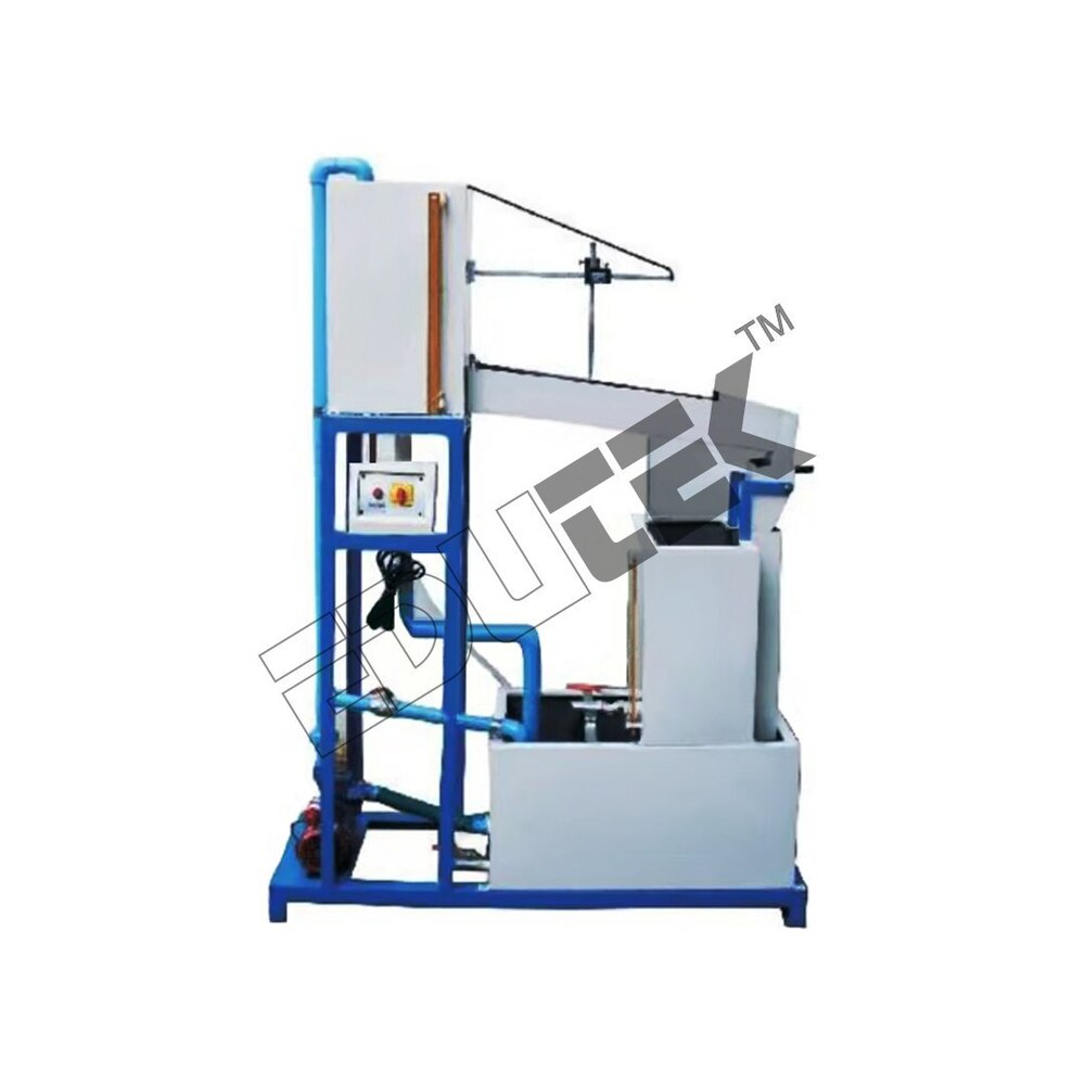
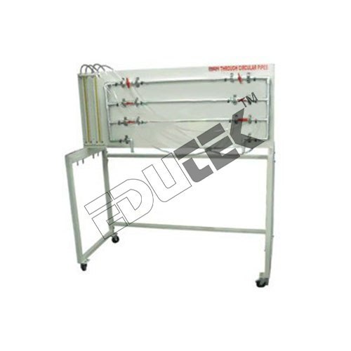
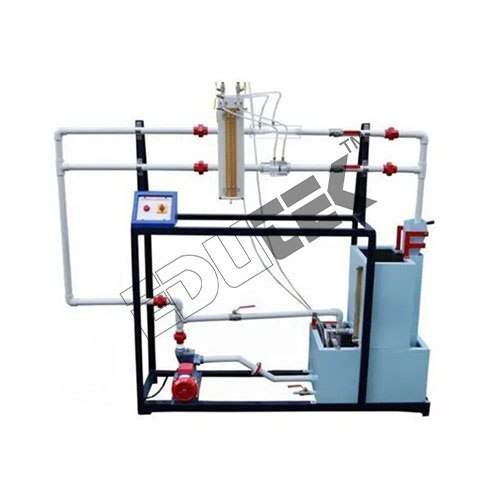
LOSSES DUE TO FRICTION IN PIPE LINES
Price: 500 INR/Piece
Specification: LOSSES DUE TO FRICTION IN PIPE LINES We offer highly demanded Losses due to friction in pipe line at the most competitive market price. Manufactured in accordance with the industry laid parameters, offered apparatus is highly demanded around the globe. The setup is designed to study the losses due to friction in pipes of different diameters and materials. This consists of a set of 3 different pipe test sections, supply tank, measuring tank and pump for closed loop water circulation. Experiments: To determine the losses due to fiction in pipes Utilities Required: Electric supply 0.5 kW, 220V AC, Single Phase Water supply Tap water connection BSP Distilled water 60 liters (optional) Floor Area with Drain facility Technical Specifications: Pipes (2 Nos.): Material GI of 1/2 & 1 diameter. Pipe Test Section Length: 1 m. Instruction Manual: An ENGLISH instruction manual will be provided along with the Apparatus
 (ET-606X)
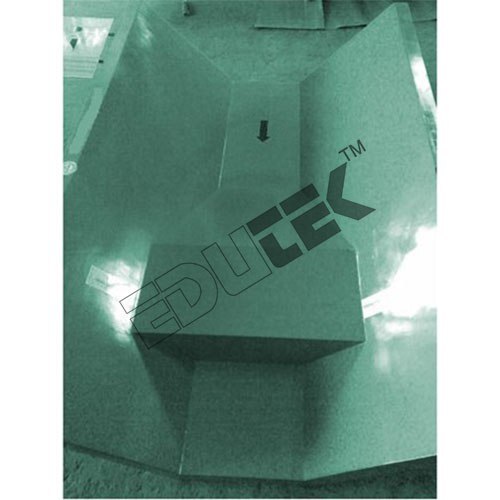
HUMP .
Price: 500 INR/Piece
Specification: HUMP Objectives To study the variation in flow due to introduction of different types of humps or weirs in the flume. Flow Characteristics over Hump Hump It is a structure or obstruction that is constructed across a river or stream to raise the level of water on upstream side so that it can be diverted to canals to meet the irrigation requirements.
 (EDK-3075)
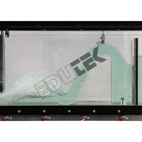
SIPHON SPILLWAY
Price: 500 INR/Piece
Specification: SIPHON SPILLWAY Made of transparent plexiglass, 3mm thickness, Dimensions: 100x216x287h, Support made of black anodized aluminum, designed for, Installation on sliding trolleys on the channel, Overall dimensions: 299x360x350h mm.
 (EDK-2607)
CRUMP WEIR
Price: 500 INR/Piece
Specification: CRUMP WEIR A crump weir model to demonstrate alternative flow measurement techniques used in rivers and waterways.
 (ET-569R)
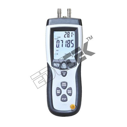
PITOT TUBE & MANOMETER BOARD
Price: 500 INR/Piece
Specification: PITOT TUBE & MANOMETER BOARD 5 Selectable Units Of Pressure Measurement 5 Selectable Units Of Pressure Measurement Large Backlit LCD Display Easy To Calculate The Area Of A Rectangular Or Circular Duct
 (ET-622V)
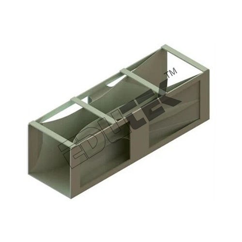
VENTURI FLUME
Price: 500 INR/Piece
Specification: VENTURI FLUME A venturi flume is a critical-flow open flume with a constricted flow which causes a drop in the hydraulic grade line, creating a critical depth. It is used in flow measurement of very large flow rates, usually given in millions of cubic units Product Specification Usage/Application: Educational purposes Material: Stainless Steel Phase: Single Phase Accuracy: 100% Country of Origin: Made in India
 (ETBH-58)
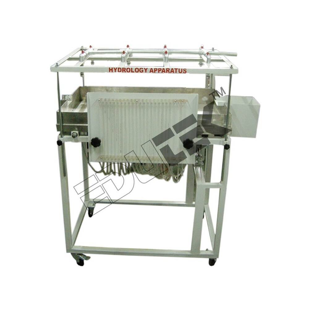
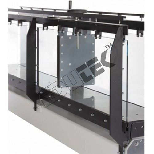
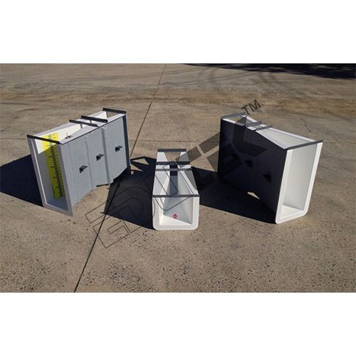
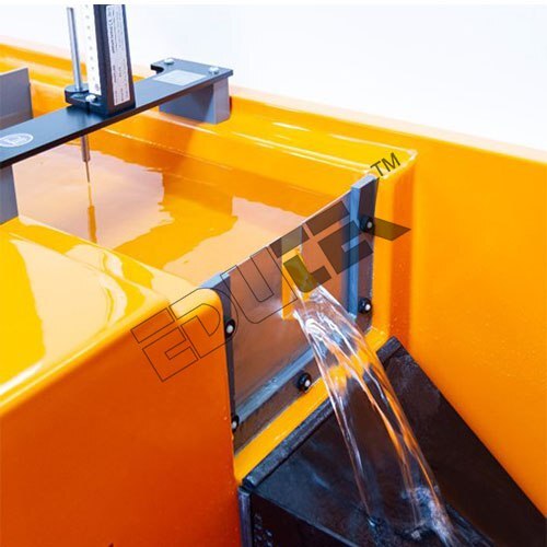
BASIC HYDROLOGY SYSTEM
Price: 500 INR/Piece
Specification: BASIC HYDROLOGY SYSTEM Technical Data Tank: Stainless steel 100 cm wide x 200 cm long x 19 cm high. Inclination: 0-3%. End compartments: 2 ea. Wells: 2 ea. Spray nozzles: 8 nozzles with separate shutoff valves. Flow measurement Rain water: Variable area flow meter. Run off: Calibrated weir. Manometer: 1 ea. Upper walls: Clear acrylic. Accessories: - Rectangular ring, circular ring, confined equifer, cylindrical pier. Power supply: 220 V, 1 Ph, 50 Hz. Other power supply is available on request. Typical Tests Investigation of rainfall/runoff relationships for dry, saturated and impermeable catchments of various slopes for surface runoff. Effect of interflow on outflow hydrograph. Simulation of multiple and moving storms. Cone of depression for single well and interaction of cones of depression for two adjacent wells. De-watering of excavation sites by use of wells. Flow from a well in a confined aquifer. Demonstration of watersheds for a simulated island with rainfall and well flows. Sediment transport and meanders in simulated rivers. A metal frame supports the tank and houses a storage tank. Water is drawn from the storage tank by a pump and separately supplied to the overhead nozzles and/or the two end compartments via a flow meter and pipings with valve control. Run-off from the catchment is measured by a calibrated rectangular weir or returns directly to the storage tank.
 (EDK-2643)
SLUICE GATE
Price: 500 INR/Piece
Specification: SLUICE GATE Sluice gate with lateral sealing lips Height adjustment using hand wheel Scale to read the height of the gate opening Technical data Gate Weir plate made of PVC Head adjustment: 0150mm Dimensions and weight LxWxH: 370x263x710mm Weight: approx. 5kg
 (ET-557J)
PARSHALL FLUME
Price: 500 INR/Piece
Specification: PARSHALL FLUME The Parshall Flume is an economical and accurate way of measuring water flow in open channels and non-full pipes. Originally the flume was developed to measure surface waters, water rights apportionment, and irrigation flows. However, its use has expanded to include measuring sewage flow (both in pipe and treatment plants), industrial discharges, dam seepage, and other applications.
 (ET-401Q)
RECTANGULAR NOTCH WEIR
Price: 500 INR/Piece
Specification: RECTANGULAR NOTCH WEIR Rectangular Weir: A rectangular notch is a thin square edged weir plate installed in a weir channel
 (ETIJA-52)
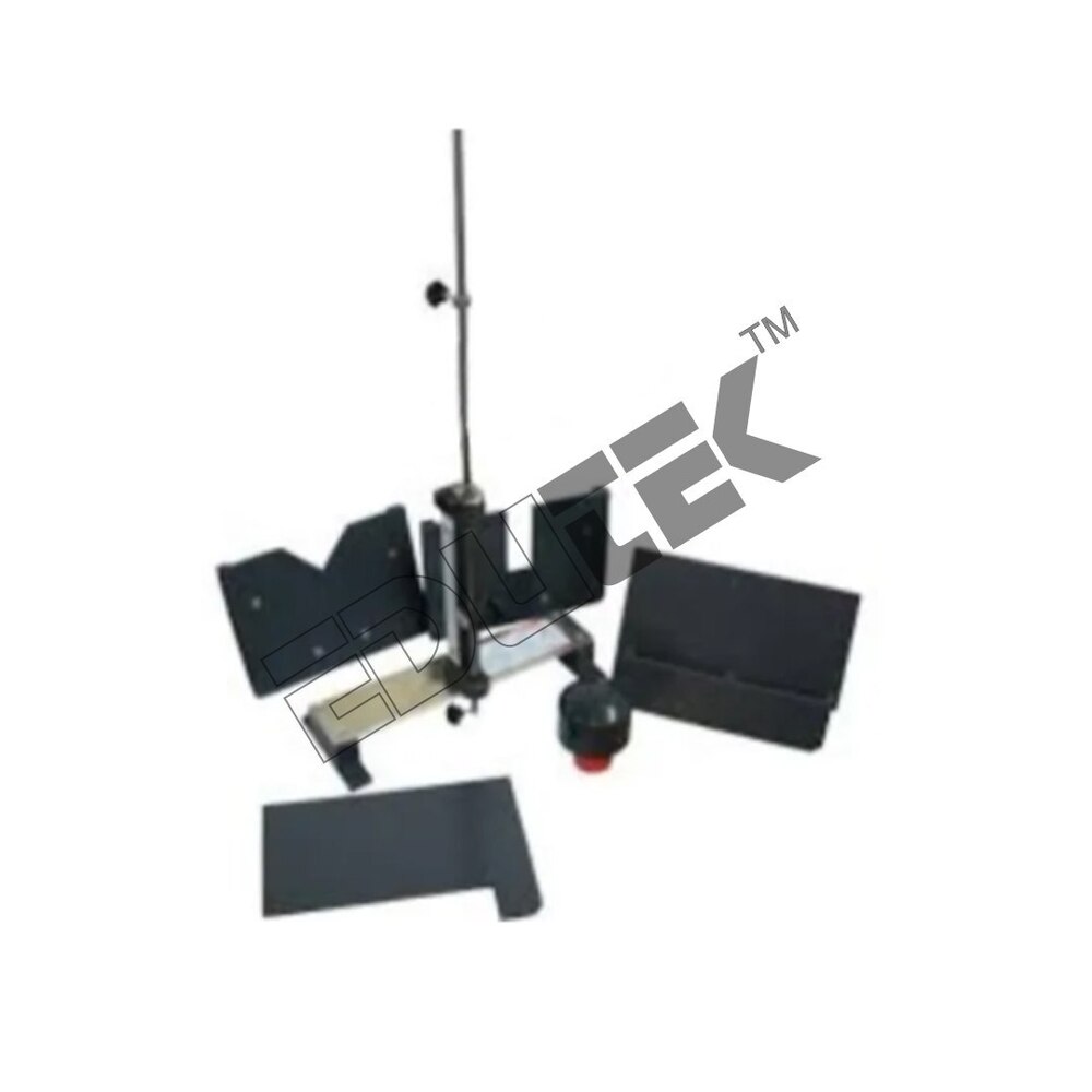
IMPACT OF JET ON VANES
Price: 500 INR/Piece
Specification: IMPACT OF JET ON VANES We are counted among the most prominent manufacturers, traders and exporters of high-quality Impact of jet of vanes. Designed in compliance with industry leading parameters, It is used to study the forced developed of a jet of water on different surfaces and to compare it with momentum theory. Offered set up consists of visible test enclosure, supply tank, measuring tank and pump for closed loop water circulation. Description The setup consists of a two-sided clear fabrication section. Water is fed through a nozzle and discharged vertically to strike a target carried on a stem which extends through the cover. A weight carrier is mounted on the upper end of the stem. The dead weight of the moving parts is counter balanced by a compression spring. The vertical force exerted on the target plate is measured by adding the weights supplied to the weight pan until the mark on the weight pan corresponds with the level gauge. A total of two targets are provided, a flat plate and a hemispherical cup. Experimentation: To measure the force developed by a jet of water impinging upon a stationary object and comparison with the forces predicted by the momentum theory Utilities required: Hydraulic Bench
 (ET-244B)
FLOW THROUGH ORIFICE & MOUTH PIECE
Price: 500 INR/Piece
FLOW THROUGH ORIFICE & MOUTH PIECE Product Specification Material: Mild Steel Finishing Type: Powder Coated ISO Certified: AN ISO 90012015 Product Description: Our company offers optimum quality Orifice and Mouthpiece Apparatus at the most reasonable market price. This apparatus is manufactured under the supervision of expert professionals, using best quality raw materials. The apparatus manufactured by us is used for the purpose of measuring fluid flowing through an open channel. Offered apparatus is exclusively demanded in various hydraulic industries for accurate performance and hassle-free installation. Experiments: To determine the co-efficient of discharge of different Orifice and mouthpiece Utilities Required: Electric supply 0.5 kW, 220V AC, Single Phase Water supply Tap water connection BSP Distilled water 60 liters (optional) Floor Area with Drain facility Technical Specifications: Sudden Enlargement: From 13 mm to 23 mm Sudden Contraction: From 20 mm to 16 mm Electric supply: 0.5 kW, 220V AC, Single Phase
 (ET-475B)
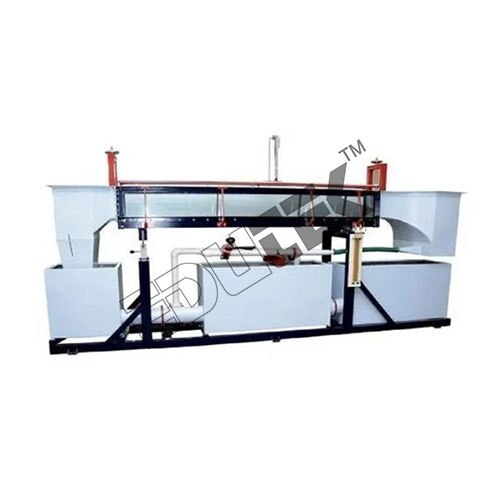
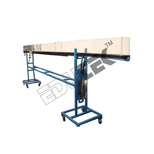
TILTING BED FLOW CHANNEL (LENGTH; 2.5M) WITHOUT ACCESSORIES
Price: 500 INR/Piece
Specification: TILTING BED FLOW CHANNEL (LENGTH; 2.5M) WITHOUT ACCESSORIES This apparatus consists of a Flow channel. Channel is fabricated from transparent Toughened Glass and Stainless Steel together. The equipment is designed to study the various phenomenon of flow with the help of various types of blocks, gates, weirs, and other many types of accessories (Optional). The channel section is transparent by which user can observe the various flow patterns of fluid in the channel and photographs can be taken. These glass panels are sealed with the stainless steel bed. This channel is floor mounted. Instrument rail is provided along the entire working length of the flume. A scale is provided along with the rail. A pointer gauge is provided to measure the depth of flow that can move on the rail. At the inlet of the flume an inlet tank with stilling and smoothing device is provided for obtaining the excellent velocity profile in the test section. At the discharge side a gate is provided which have an adjustable height. This gate maintains the operating water levels for the flume. This flume is tilted using a jacking system which has one jack. An arrangement has been done to calculate the slop of channel. The flow channel is self-contained re-circulating unit provided with sump tank, centrifugal pump, and control valve. Water is circulated through the channel by centrifugal pump. The pump draws water from sump tank to inlet tank of flume and return back to sump after passing through the channel. Product Details: Automatic Grade: Manual Voltage: 220 V Backrest Adjustment: 0-75 Deg Capacity: 240 Kg Footrest Adjustment: 0-40 Deg Height Adjustment: 575 - 815 mm
 (EDK-3012)
V-NOTCH WEIR
Price: 500 INR/Piece
Specification: V-NOTCH WEIR Product Features Vibrating Wire precision water level sensor Simple in, low cost and robust instrument Accurate and sensitive water level monitoring High resolution monitoring Low maintenance system Range: 300mm Resolution*: 0.025% full scale (minimum) Material: Stainless Steel
 (ET-314Z)
STANDING WAVE FLUME
Price: 500 INR/Piece
Specification: STANDING WAVE FLUME FRP Standing Wave Flumes used for discharge measurement in channels and laboratories are experimentally investigated. Height and width of SWF are the two parameters characterizing the head-discharge relationship. Laboratory experiments are conducted by measuring the discharge and the head over the weir for variable weir heights and widths. Applicability of various formulations for the discharge coefficient are investigated. Specifications: Material: FRP Size: Customized
 (EDK-2823)
SPILLWAY .
Price: 500 INR/Piece
Specification: SPILLWAY Made of transparent plexiglass 8 mm thickness, Overall dimensions: 200x200x310h mm, Include: Hydraulic jump made of transparent plexiglass and black PVC, Overall dimensions: 150x299x70h mm, Breakwaters: made of black PVC, Overall dimensions: 96x10x170h mm, Apron with Energy Dissipaters made of black PVC, Overall dimensions: 300x299x45h - Wooden Dam, Made of black PVC overall dimensions: 299x400x150h mm.
 (ET-211M)
LOSSES DUE TO PIPE FITTING, SUDDEN ENLARGEMENT & CONTRACTION
Price: 500 INR/Piece
Specification: LOSSES DUE TO PIPE FITTING, SUDDEN ENLARGEMENT & CONTRACTION The set up consists of a 1/2 bend and elbow, a sudden expansion & sudden contraction fitting from 15mm to 25mm, ball valve and gate valve. Pressure tapings are provided at inlet and outlet of these fittings under test. A differential manometer fitted in the line gives pressure loss of individual fittings. Present setup is self-contained water re-circulating unit, provided with a sump tank and a centrifugal pump etc. Flow control valve and by-pass valve are fitted in water line to conduct the experiment on different flow rates. Flow rate of water is measured with the help of measuring tank and stop watch. Control Panel Comprises Of: Standard Make On/off Switch, Mains Indicator, Etc. Sump Tank Capacity: 50 Ltrs Flow Measurement: Using Measuring Tank with Pedometer, Capacity: 25 Ltrs Manometer Fluid: Mercury (Hg) - 250 Gm Sudden Enlargement: From 15 mm to 25 mm Sudden Contraction: From 25 mm to 15 mm Bend: 1/2 Elbow: 1/2 Ball Valve: 1/2 Gate Valve: 1/2 Inches Water Circulation: FHP Pump, Crompton Makes Pressure Drop Measurement: Differential Manometer Stop Watch: Electronic
 (ET-696R)
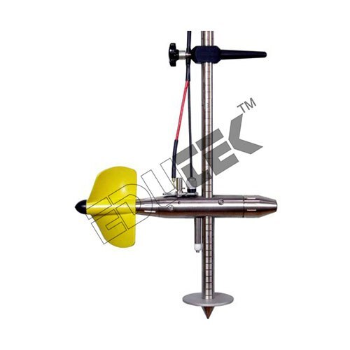
CURRENT METER
Price: 500 INR/Piece
Specification: CURRENT METER Fluid: for water Installation: vertical Material: stainless steel Protection level: corrosion-resistant Other characteristics: precision
 (ET-5342)
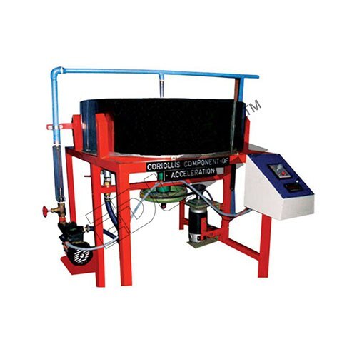
CORIOLLIS COMPONENT OF ACCELERATION APPARATUS.
Price: 500 INR/Piece
CORIOLLI™S COMPONENT OF ACCELERATION APPARATUS We are offering a wide range of Coriolis Component Acceleration. This entire set up is designed to study various coriolis components of a slider crank mechanism. In this process the continuous stream of water which is flowing through a steady rotating pair of tubes replaces mechanical slider system. The tubes of the system can be easily rotated in various speeds with the usage of a swinging field motor which also serves a dynamometer. There is a Perspex window located on the top of the tank. This window assures complete clear view of the process. It also prevents the splashing of water over the side of the tank. The in-built dynamometer continuously measures the torque which is applied to the various rotating tubes. This entire equipment is self-contained. The re-circulating of the water is assisted with a own speed control unit and water circulating pump which is separate. Experimentation To determine Coriolis Component of Acceleration at various speeds of rotation and water flow rates Utilities Required Electricity 0.5 kW, 220 V, Single Phase Drain Water Supply Technical Details: Swinging field type, variable speed Pump, FHP The whole set-up is well designed and arranged in a good quality painted structure Fabricated out of stainless steel Rotating arms 9mm/6mm orifice diameter, length 300 mm Rotameter, Electric motor, Main tank Control Panel comprises of: Speed control unit Standard make On-Off switch, mains indicator RPM indicator with proximity sensor RPM measurement
 (EDK-2247)
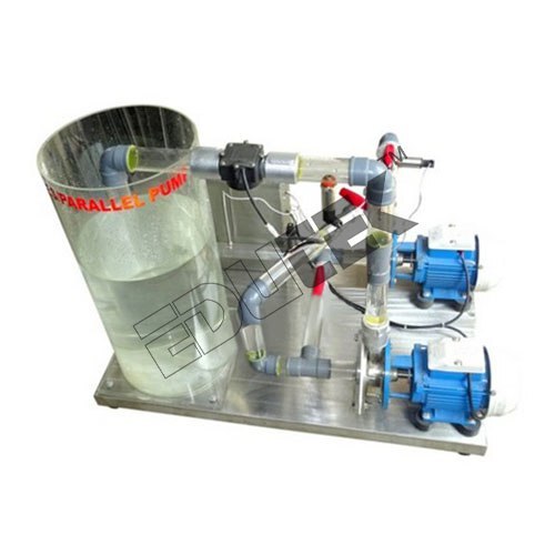
SERIES & PARALLEL SYSTEM CENTRIFUGAL PUMP DEMONSTRATION
Price: 500 INR/Piece
Specification: SERIES & PARALLEL SYSTEM CENTRIFUGAL PUMP DEMONSTRATION Two motor-driven centrifugal pumps, mounted on a stainless steel plinth with a water reservoir and pipework for continuous circulation. The pumps can be configured for single pump operation, two pumps in parallel or two pumps in series by using manually operated ball valves. Similarly, manual valves are used to control the flow and facilitate the study of suction effects, including demonstration of air release. In parallel operation the two pumps draw from a shared inlet pipe of a wider diameter than the pump inlet, reflecting a typical industrial configuration of parallel pumping. Each pump has impellers that can be easily accessed and replaced without tools. This is delivered with three impellers in total one with forward curved blades and two with backward curved blades allowing the students to investigate the effects of impeller characteristics. Electronic sensors measure the pump outlet pressure of each pump the shared pump inlet pressure the flow rate and the water temperature.
 (ETFTC-56)
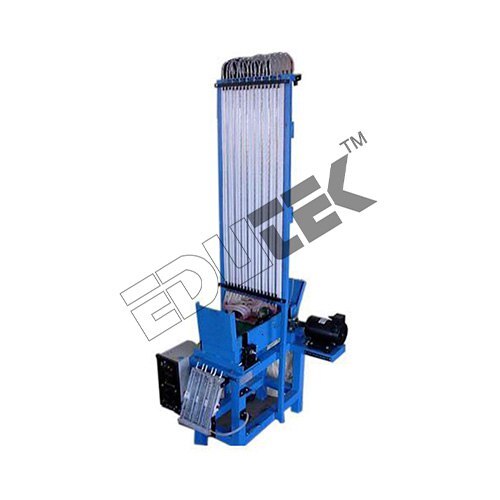
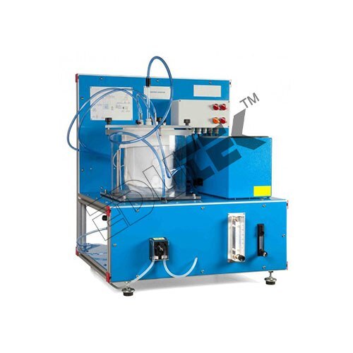
FLUID FRICTION APPARATUS.
Price: 500 INR/Piece
Specification: FLUID FRICTION APPARATUS Fluid Friction Apparatus Shows flow and losses in different pipes, fittings and valves. Shows popular flow measurement instruments. A space-saving vertical panel that works with Gravimetric or Volumetric Hydraulic Benches for easy installation Includes different valves, pipes and fittings to show losses Includes experiments on roughened pipes Shows laminar and turbulent flow Uses Bernoulli™s equation Shows how to use Venturi and orifice meters to measure flow Includes a traversing Pitot tube to measure velocity profile Fluid Friction Apparatus allows students to study flow, flow measurement techniques and losses in a wide variety of pipes and fittings. The equipment has three water circuits with instruments, pipes and pipe system components. These allow students to examine and compare the different component characteristics. A hydraulic bench (Gravimetric) or Volumetric, available separately) supplies the circuit with a controlled flow of water. A space-saving vertical panel holds all the parts for easy use. To measure pressure loss across components, students use a piezometer set and differential pressure gauge (included). To perform experiments students record the temperature of water in the hydraulic bench and set the hydraulic bench to pump water through a circuit. They measure pressure losses across instruments or components. The hydraulic bench gives an external flow rate for reference and comparison. The flow measurement instruments show students the common methods of measuring water flow. They also give applications of the steady flow energy equation (Bernoulli™s equation). Students use a Venturi meter and an orifice plate meter and compare the losses of each. They also find the losses in a rapid enlargement. The equipment also includes a Pitot-static tube. By traversing the Pitot across the pipe diameter, students can find the velocity profile and flow coefficients. They also find the relationship between the flow rate and pressure differential. An artificially roughened pipe allows students to study friction factor at different Reynolds numbers, covering the interesting transitional flow from laminar to turbulent. They can compare results to those predicted by Nickuradse™s results and a Moody chart. Standard Features: Supplied with a comprehensive user guide. Two-year warranty. Manufactured in accordance with the latest Indian Union directives.
 (ET-670P)
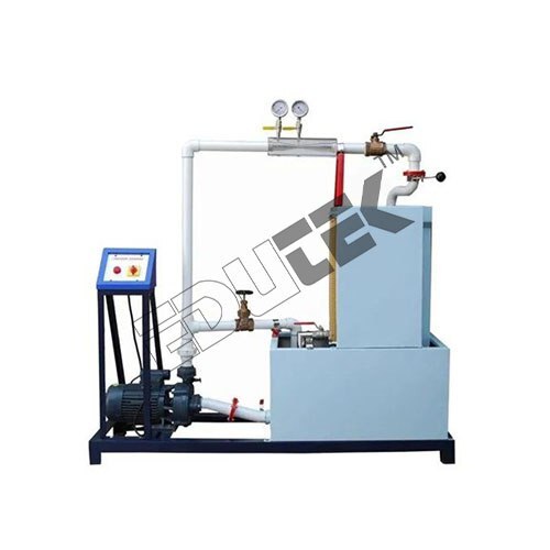
CAVITATIONS APPARATUS.
Price: 500 INR/Piece
Specification: CAVITATIONS APPARATUS The apparatus has been designed to demonstrate the phenomenon of cavitation. The present set-up consists of a test section made of Acrylic having conversion and diversion section. Pressure tapings at appropriate position are provided. This test section is having one control valve at upstream side to regulate the water flowrate. Two pressure gauges are connected to these taping which give the pressure readout at the time of flow passing through this test section. Present set-up is self-contained water re-circulating unit, provided with a sump tank, centrifugal pump etc. Water is pumped by means of centrifugal pump and passing through the test section, it returns back to the sump which make the system re-circulating type. Flow of water is diverted either to measuring tank or sump tank with the means of a flow diverter, when needed. Flow control valve and by-pass valve are fitted in water line to conduct the experiment on different flow rates. Flow rate of water is measured with the help of measuring tank with piezometer and stopwatch. The supplied set-up is complete in all respect. Only water supply and electricity supply is to be provided by the end user for running the set-up. Product Specification Test Section: Material Acrylic Pressure Gauge: 0-4 kg/cm2 Vacuum Gauge: 0-760 mmHg Water Circulation: By Pump, Crompton/Standard make. Flow Measurement: Using Measuring Tank, Capacity 40 liters Sump Tank Capacity: 60 Ltrs. Stop Watch: Electronic
 (ED-57528)
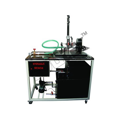
HYDRAULIC BENCH WITH 11 ACCESSORIES
Price: 500 INR/Piece
Specification: HYDRAULIC BENCH WITH 11 ACCESSORIES We are manufacture Export Quality Hydraulic Bench for Fluid Mechanics Laboratory. Hydraulic bench is a very useful apparatus in hydraulics and fluid mechanics. The Hydraulic Bench is designed as a portable and self-contained service module for the range of accessories to carry out experimentation on principles of Fluid Mechanics. Wide range of accessories are available for use with Hydraulic Bench that cover a number of experiments to study principles of fluid mechanics. The whole set-up is well designed and arranged in a good quality painted structure Experiment of Hydraulic Bench Bernoullis Theorem Apparatus Flow measurement by Venturimeter Flow measurement by Orificemeter Flow over Notch Orifice and Mouth Piece Losses due to Friction in Pipe Line Losses in Pipe Fitting Impact of Jet on Vane Study of Pressure Measurement Pitot Tube Free Vortex Apparatus Technical Specifications of Hydraulic Bench Water Circulation 1 HP Pump, Crompton/ Kirloskar make. Flow Measurement: Using Measuring Tank, Capacity 40 Ltrs. Sump Tank Capacity Stop Watch Electronic. Control Panel Comprises of: Standard make On off Switch, Mains Indicator, etc. Instruction Manual: An English instruction manual will be provided along with the Apparatus Tanks and Top Tray will be made of Stainless Steel.
 (ETOF-40 )
ORIFICE & JET VELOCITY APPARATUS
Price: 500 INR/Piece
Specification: ORIFICE & JET VELOCITY APPARATUS In the Orifice & Free Jet Flow accessory a constant head tank is fed with water from the Hydraulics Bench. The orifice is installed at the base of this tank by means of a special wall fitting, which provides a flush inside surface. The head is maintained at a constant value by an adjustable over flow and is indicated by a level scale. A series of adjustable probes enable the path followed by the jet to be ascertained. Demonstration Capabilities:- Establishing the coefficient of velocity for a small orifice. Finding the coefficient of discharge for a small orifice with flow under constant head and flow under varying head. Comparing the measured trajectory of a jet with that predicted by simple theory of mechanics Establishing the coefficient of velocity for a small orifice Finding the coefficient of discharge for a small orifice with flow under constant head and flow under varying head Comparing the measured trajectory of a jet with that predicted by simple theory of mechanics Technical Specifications:- Orifice diameters: 3.0 mm and 6.0 mm Jet trajectory probes: 8 Max constant head: 410 mm
 (ET-83343)
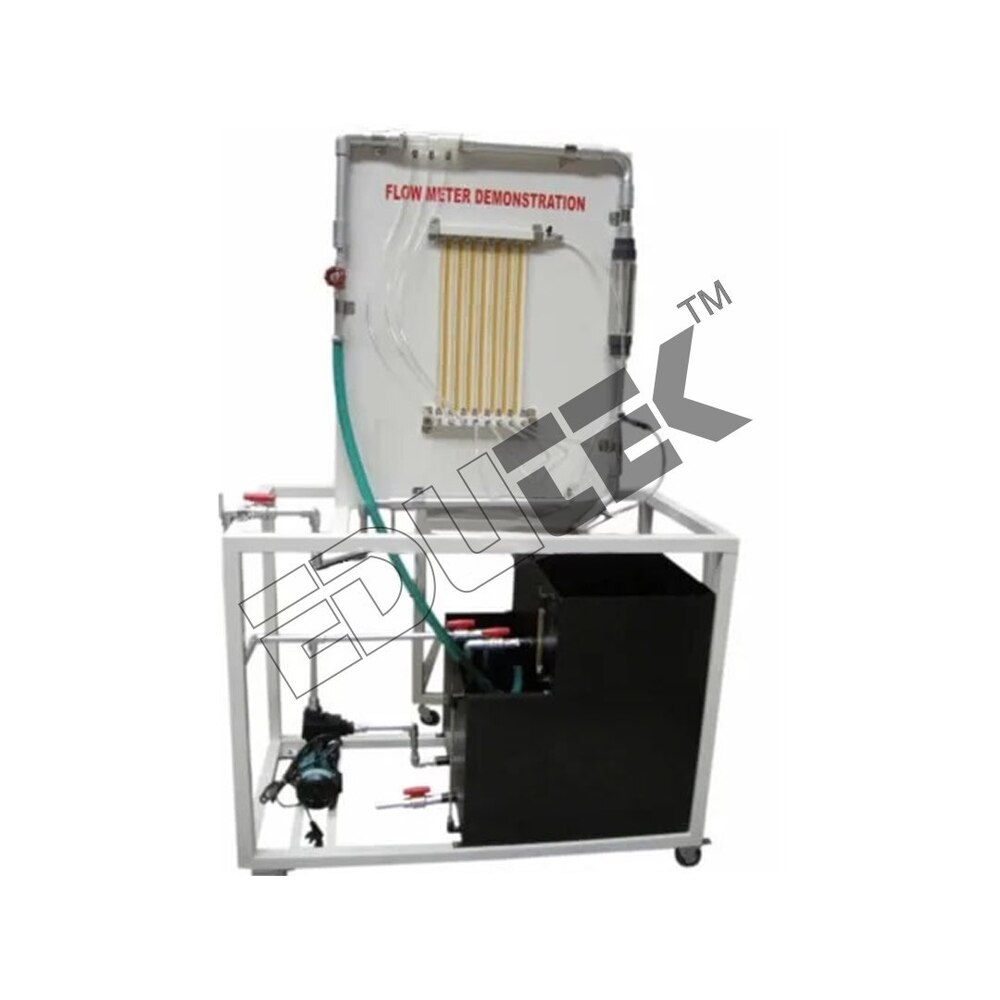
FLOW METER DEMONSTRATION
Price: 500 INR/Piece
Specification: FLOW METER DEMONSTRATION The Flow Meter Demonstration Unit is a self-contained facility to demonstrate the important characteristics of flow meters. The main elements are a service module and flow meter support stand. A self-priming centrifugal pump draws water from the sump tank in the service module and delivers it to a flow meter test pipe. Industrial type flow meters mounted in test sections can be fitted into the test pipe quickly and easily. These meters have been chosen to give a variety of different metering principles and degrees of sophistication and accuracy. Some of the meters are calibrated directly in units of flow, whilst others involve the use of calibration charts. The pressure drop across each of the flow meters can be measured by using either the one meter pressurized water manometer or the 0.5 meter mercury manometer supplied. Ported manometer connection valves ensure rapid bleeding of all manometer pipe work. A facility exists to admit air into the hydraulic stream to demonstrate the effect on the meter™s accuracy. The discharge from the test section is controllable and is fed through a diffuser into the channel of the service module. Demonstration Capabilities:- Comparing the use application and limitations of various types of flow meter Considering the implications of flow meter selection on performance, accuracy, convenience, cost and head loss Understanding the principles on which different types of flow meter are based Relating pressure drop across a flow meter to flow rate Using manometers to measure pressure drop Investigating the effect of air in the hydraulic stream on flow meter performance Understanding the application of Bernoulli™s Theorem Technical Specifications:- Maximum flow rate: 2.3 liters/s Reservoir capacity: 140 liters Volumetric tank capacity: 40 liters Nominal bore of pipe work: 38mm Length of removable test pipe: 750mm Pump motor rating: 0.55kW A self-contained apparatus to demonstrate the characteristics of flow meters used in measurement of water flow through pipes or open channels Service module with reservoir, volumetric measuring tank and pump Reference turbine flow meter permanently fitted Metering devices available in various combinations to suit coursework
 (ET-379T)
PITOT TUBE SET-UP
Price: 500 INR/Piece
Specification: PITOT TUBE SET-UP A Pitot tube is used to measure the local velocity at a given point in the flow stress. A pitot tube of standard design made of copper/SS is supplied and is fixed below vernies scale. The vernies scale is capable to measure the position of Pitot tube in transparent section. The pipe has a flow control valve to regulate the flow. A U-tube manometer is provided to determine the velocity head. Present set-up is self-contained water re-circulating unit, provided with a sump tank and a centrifugal pump etc. Flow control valve and by-pass valve are fitted in water line to conduct the experiment on different flow rates. Flow rate of water is measured with the help of measuring tank and stop watch. Product Specification Phase: Single Phase Material: Stainless Steel Current: 5-15 amp Frequency: 50Hz Voltage: 220V AC Floor Area Required: 1.5 x 0.75 m
 (ET-328T)
FLOW CHANNEL
Price: 500 INR/Piece
Specification: FLOW CHANNEL The channel consists of a clear acrylic working section of large depth-to-width ratio incorporating undershot and overshot weirs at the inlet and discharge ends respectively. Water is fed to the streamlined channel entry via a stilling tank to reduce turbulence. Water discharging from the channel is collected in the volumetric tank of the Hydraulics Bench and returned to the sump for recirculation. A dye injection system incorporated at the inlet to the channel enables flow visualization in conjunction with a reticule on the rear face of the channel. Models supplied with the channel include broad and sharp-crested weirs, large and small-diameter cylinders and symmetrical and asymmetrical aerofoil™s, which in conjunction with the inlet and discharge weirs, permit a varied range of open channel and flow visualization demonstrations. Demonstration & Visualisation Capabilities:- Demonstrating basic phenomena associated with open channel flow Visualization of flow patterns over or around immersed object Technical Specifications:- Clear acrylic working section fed from stilling tank Six different models for investigation Dye injection system Quick release fitting for easy connection to Hydraulics Bench Educational software available as an option Dye injection needles: 5 Dye reservoir capacity: 0.45 L
 (ET-407D)
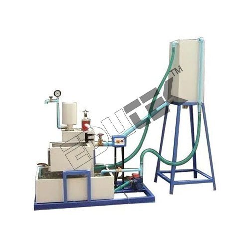
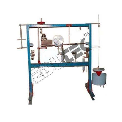
HYDRAULIC RAM DEMONSTRATION
Price: 500 INR/Piece
Specification: HYDRAULIC RAM DEMONSTRATION The Hydraulic Ram comprises an acrylic base incorporating pulse and non-return valves and a supply reservoir on a stand, which is fed by the Hydraulics Bench. An air vessel above the valve chamber smoothes cyclic fluctuations from the ram delivery the weights supplied may be applied to the pulse valve to change the closing pressure and thus the operating characteristics. Demonstration Capabilities:- Establishing flow/pressure characteristics and determining efficiency of the hydraulic ram. Technical Specifications:- Pump body manufactured from clear acrylic with stainless steel pulse and non-return valves. Adjustable acrylic header tank with inlet and outlet hoses. Outlet hose with variable head arrangement. Quick-release fitting for easy connection to Hydraulics Bench. Supplied with weights to load pulse valve. Educational software available as an option. Supply head: 300-700 mm variable. Delivery head: 750-1500 mm variable.
 (EDK-2283)
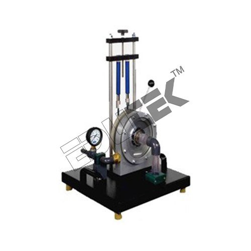
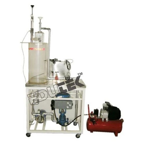
FRANCIS TURBINE DEMONSTRATION
Price: 500 INR/Piece
Specification: FRANCIS TURBINE DEMONSTRATION Features Design and function of a Francis turbine Determination of torque, power and efficiency Graphical representation of characteristic curves for torque, power and efficiency Determination of mechanical output Determination of efficiency Recording of characteristic curves Investigation of the influence of the guide vane position on the power output Velocity triangles Specification Turbine Output: approx. 350W at 1500min-1, 270L/min, H=15m Max. Speed: 3000min-1, Rotor, 11 blades Medium diameter: 60mm, Distributor, 7 vanes Angle of attack: 020 Measuring ranges Torque: 09,81Nm Pressure: 04bar abs. Speed: 04000min DIMENSIONS AND WEIGHT L x W x H: 1000-x800 x 1200 mm Weight: 90kg
 (ETFVA-58)
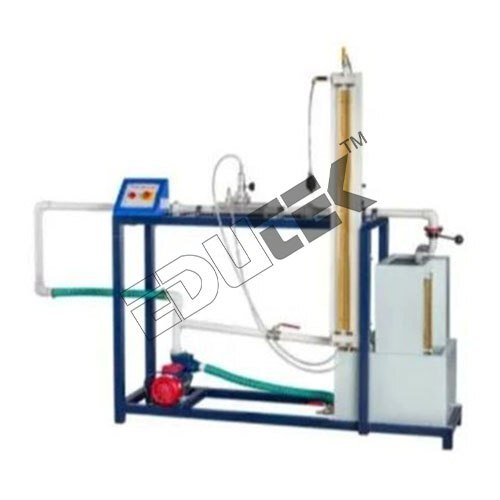
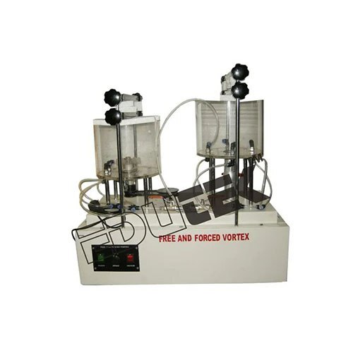
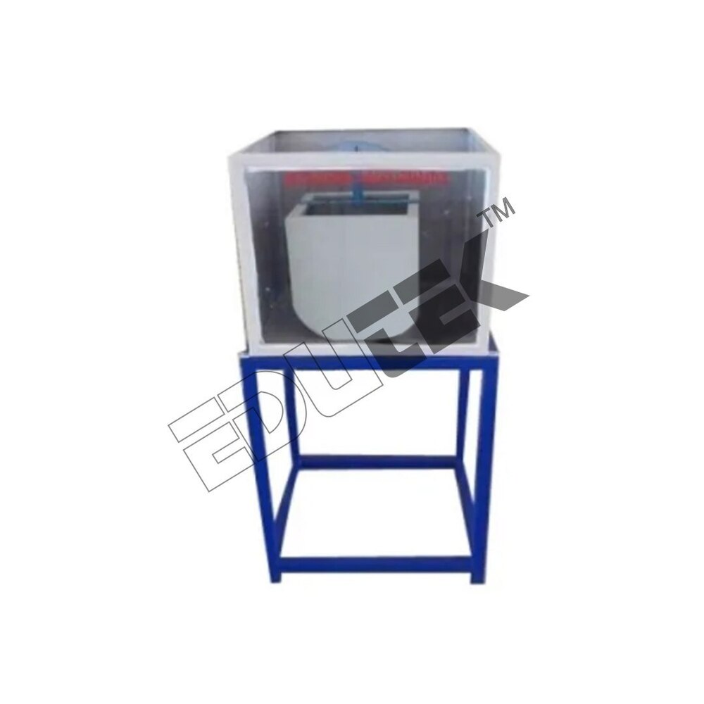
FREE & FORCED VORTEX APPARATUS.
Price: 500 INR/Piece
Specification: FREE & FORCED VORTEX APPARATUS Free and Forced Vortex Flow apparatus offered by us has been painstakingly designed by our team of expert professionals. This apparatus enables the researchers to determine the shape of the vortex profile. With the accuracy of the results it provides, this apparatus is very popular in the market. Created using optimum quality materials and cutting edge technology, this delivers flawless performance. We subject it to quality tests based on multiple parameters before making it available to the customers. Range Of Experiments To visualize the forced & free vortex phenomenon. To plot the shape of vortex profile i.e. vertical height vs horizontal radius.
 (ET-2138OD)
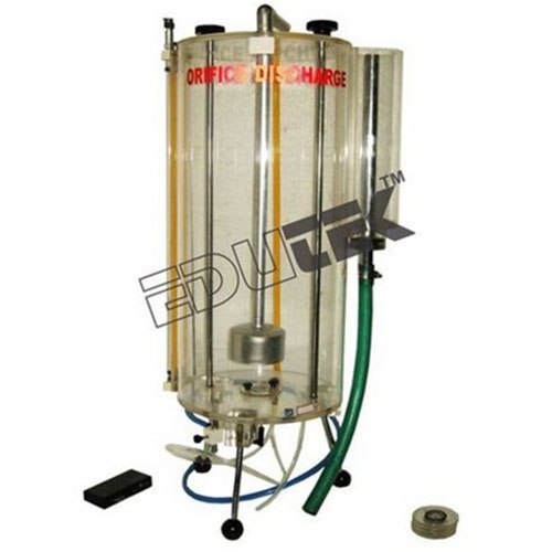
ORIFICE METER DISCHARGE
Price: 500 INR/Piece
Specification: ORIFICE METER DISCHARGE The Orifice Discharge accessory consists of a cylindrical clear acrylic tank which has an orifice fitted in the base. A traverse assembly is provided which enables a piton tube to be positioned anywhere in the jet. Attached to this piton tube is a fine wire which can be traversed across the jet to accurately measure the jet diameter and the vena contract diameter and so determine the contraction coefficient. The piton head and the total head across the orifice are shown on manometer tubes adjacent to the tank. In addition to the sharp edged orifice six additional orifices with different profiles are supplied. All orifices have a common bore of 13 mm for direct comparison of performance. Demonstration Capabilities:- Determining the contraction and velocity coefficients Calculating the discharge coefficient Technical Specifications:- Cylindrical clear acrylic tank with orifice fitted in base Seven interchangeable orifices Piton tube and wire-on micrometer to measure jet velocity and diameter Quick-release fitting for easy connection to Hydraulics Bench Educational software available as an option Traverse mechanism: Lead screw with adjusting nut calibrated 0.1mm per division Standard orifice: Sharp-edged 13mm diameter Max head: 365mm
 (EDPT-13)
PELTON WHEEL TURBINE DEMONSTRATION
Price: 500 INR/Piece
Specification: PELTON WHEEL TURBINE DEMONSTRATION This accessory comprises a miniature Pelton wheel with spear-valve arrangement mounted on a support frame, which fits on to the Hydraulics Bench top channel. Mechanical output from the turbine is absorbed using a simple friction dynamo meter. Pressure at the spear valve is indicated on a remote gauge. A non-contacting tachometer may be used to determine the speed of the Pelton wheel. Basic principles of the Pelton turbine may be demonstrated and, with appropriate measurements, power produced and efficiency may be determined. Demonstration Capabilities:- Determining the operating characteristics, ie power, efficiency and torque, of a Pelton turbine at various speeds Technical Specifications:- Turbine wheel inside cast housing with acrylic panel to enable viewing Mechanical torque measured using dynamometer with spring balances Inlet pressure gauge Quick-release fitting for easy connection to Hydraulics Bench Educational software available as an option Speed range: 0-2000 rpm Brake power: 10W Pressure gauge range: 0-25 m H2O Force balance range: 0-20 N x 0.2 N Number of Pelton buckets: 16 Diameter of Pelton wheel: 123 mm
 (ETMH-60)
METACENTRIC HEIGHT APPARATUS.
Price: 500 INR/Piece
Specification: METACENTRIC HEIGHT APPARATUS Metacentric Height Apparatus Complete with Collecting Tank: Edutek For the purpose of providing the best Metacentric Height Apparatus to our clients, we use raw materials of the finest quality and strictly as per the set industrial standards, the quality standard never deteriorates. Made available in the market at a very competitive price, the offered product of impeccable functionality and efficiency, is one of the best available in the market. Technical Specifications: Pontoon: Size 300 x 300 mm (approx.) with a Horizontal Guide Bar for aliding weight and Removable Strips, Graduated arc with Pointer with moveable hanger And set of weights Water Tank: Size 550 x 500x 400 mm (approx.) Front Window of Tank: Made of Glass/Perspex A set of weights is supplied with the apparatus Instruction Manual: An ENGLISH instruction manual will be provided along with the Apparatus Tanks will be made of Stainless Steel Pendulum and graduated are for accurate measurement of Tilt angle
 (ETE-2127D)
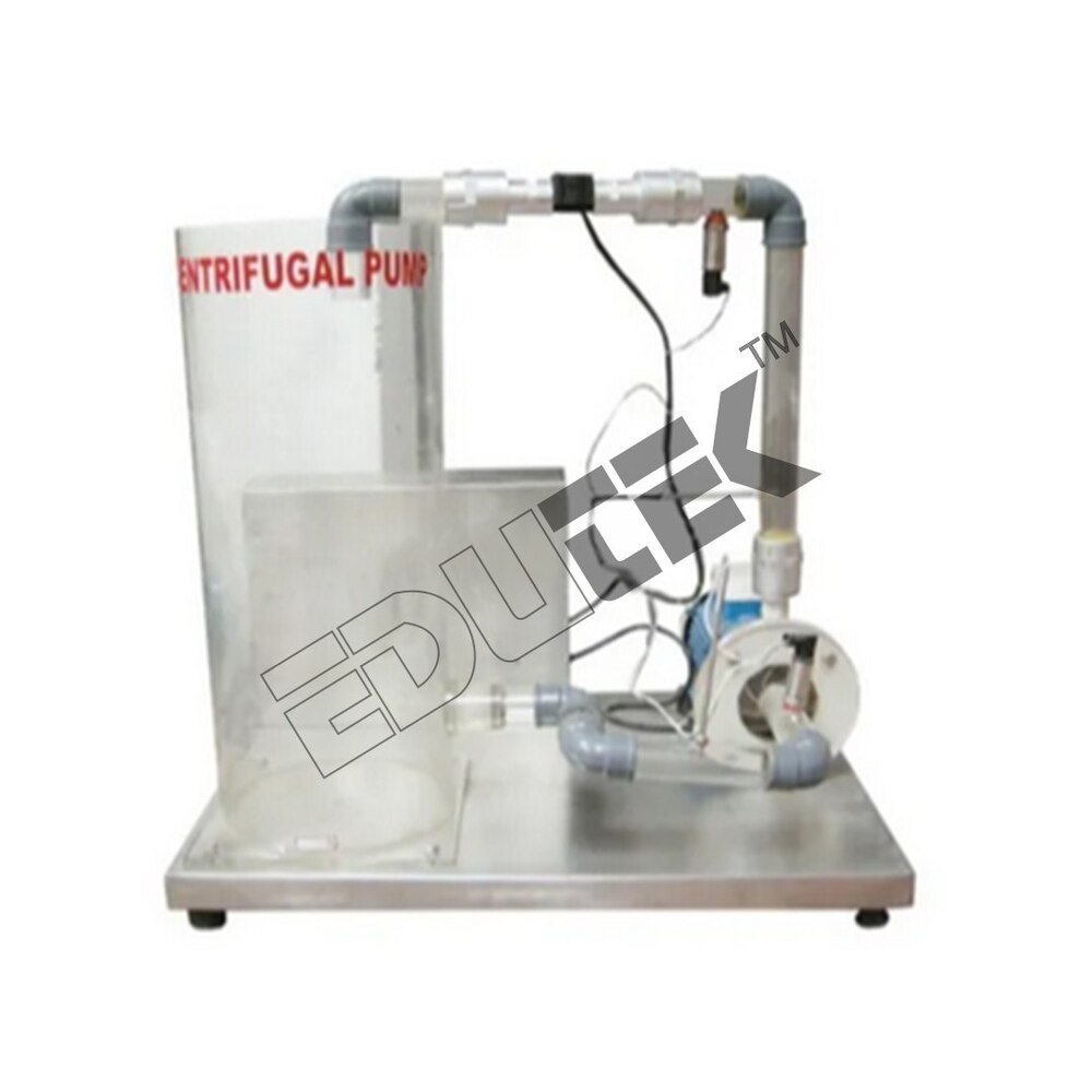
CENTRIFUGAL PUMP DEMONSTRATION
Price: 500 INR/Piece
Specification: CENTRIFUGAL PUMP DEMONSTRATION The centrifugal pump is the machine most commonly used to move liquids from one place to another. As such it is a particularly instructive unit with which to introduce students to the whole subject of rot dynamic fluid machines. A motor driven centrifugal pump, mounted on a stainless steel plinth with a water reservoir and pipework for continuous circulation. The pump volute and the water reservoir are manufactured from clear acrylic for maximum visibility. Similarly the pipe runs are made from transparent PVC. Manually operated valves at the pump inlet and outlet allow control of the flow and also facilitate the study of suction effects. The pump volute has been designed so that the impeller can be easily accessed and replaced without tools. This is delivered with two impellers, one with forward curved blades and one with backward curved blades, allowing the students to investigate the effects of impeller characteristics. Electronic sensors measure the pump inlet pressure, the pump outlet pressure, the flow rate and the water temperature. Features:- Demonstration of a single-stage centrifugal water pump in operation. Measurement of inherent-speed pump performance, including production of characteristic curves: Pump total head Motor input power Impeller speed Overall total efficiency Introduction to pump speed laws. Investigation of impeller styles. Comparison of student calculations with computer results. Technical Specifications:- Max flow rate: 6 L/min typical Max head: 9.0 m Max pump speed: 1800 rpm Motor power rating: 180 W
 (ET-471X)
FLOW VISUALIZATION (HELESHAW) APPARATUS
Price: 500 INR/Piece
Specification: FLOW VISUALIZATION (HELESHAW) APPARATUS Heleshaw App. is used to demonstrate the flow pattern of liquid for variuos types of models such as Circular shape, Square shape, Triangular shape, aero foil shap. ..etc.,
 (ET-452R)
STUDY OF PRESSURE MEASUREMENT
Price: 500 INR/Piece
Specification: STUDY OF PRESSURE MEASUREMENT This is a board mounted model which demonstrates various types of pressure measurement devices used in common practice. The devices incorporated are: o Single well Manometer o Differential Manometer o Sensitive Manometer o Pressure Gauge o Vacuum Gauge These devices are coupled to suction and discharge piping of Hydraulic Bench Pump and a close circulation system is established, with this set up, the working and operating principle of the pressure measuring devices can be studied. Product Description Phase : Single Phase Usage/Application : Pressure Measurement Packaging Size : Box Voltage : 220 Volt Material : Stainless Steel Automation Type : Automatic
 (ET-533E)
VENTURI-METER & ORIFICE METER
Price: 500 INR/Piece
Specification: VENTURI-METER & ORIFICE METER Voltage: 220-240V Body Material: Mild Steel Measuring Tank: 32 Liters Throat Diameter: 16 mm Sump Tank: 100 Liters Orifice meter Material: Clear Acrylic Compatible to 1 Inch
 (ETRA-59)
REYNOLDS S APPARATUS
Price: 500 INR/Piece
Specification: REYNOLDS™S APPARATUS It is manufactured at our unit by using highest quality materials under the guidance of the experts. This is extensively used to illustrate laminar, transitional and fully turbulent pipe flows. It also determines the conditions under which the flow occurs. Reynolds Apparatus can be availed by our customers at an economical price. Features: Accurate result Enhanced functional life Easy to use Product Specification Frequency: 50 Hz Voltage: 220 Volt Phase: Single Phase Current: 5-15 amp
 (ET-995E)
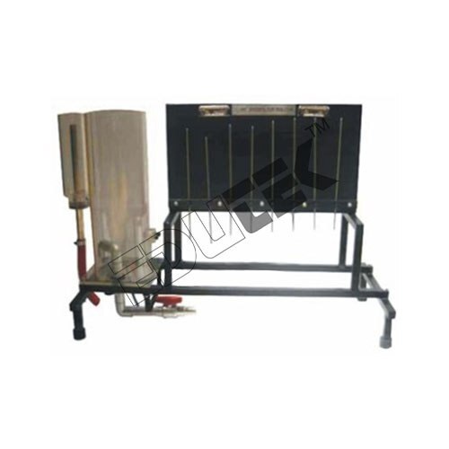
DRAINAGE & SEEPAGE TANK APPARATUS
Price: 500 INR/Piece
Specification: DRAINAGE & SEEPAGE TANK APPARATUS The present set-up is designed to study the flow through permeable media. This apparatus consists of a tank whose bed is made from Stainless Steel. The sides of the tanks are supported and sealed so that it allows free access to the interior. One side of the tank is of Toughened glass to give good scratch free visibility over a long period of use and minimum sight obstruction. Second side is of Stainless Steel and required pressure tapings are mounted on the same. The tank has two adjustable overflows close to the each end so that constant head of water can be maintained in each half of the tank. These may be lowered to a position close to the bed of the tank for some experiments to provide sub soil drainage. Present set-up is self-contained water circulating unit with sump tank, Pump, flow control valve etc. Product Specification Drainage or Seepage Tank: Length 1500 mm Width 100 mm Tank Base: Stainless Steel or Aluminum Front Side: Toughened Glass (Front Side) Back Side: Stainless Steel Sump Tank: Stainless Steel, Capacity 100 Ltrs. Pump: FHP Pump, Crompton Make.
 (ET-5348)
MICHEL TILTING PAD BEARING APPARATUS
Price: 500 INR/Piece
Specification: MICHEL TILTING PAD BEARING APPARATUS Edutek Our firm is offering Michell Tilting Pad Bearing Apparatus to our consumers. These are designed with utmost precision by our experienced professionals using ultra-modern machines and equipment. Before the final delivery, these products are stringently examined on various grounds by our quality analyzers to ensure their flawlessness. Available at a very low market rates
 (ET-5336)
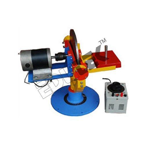
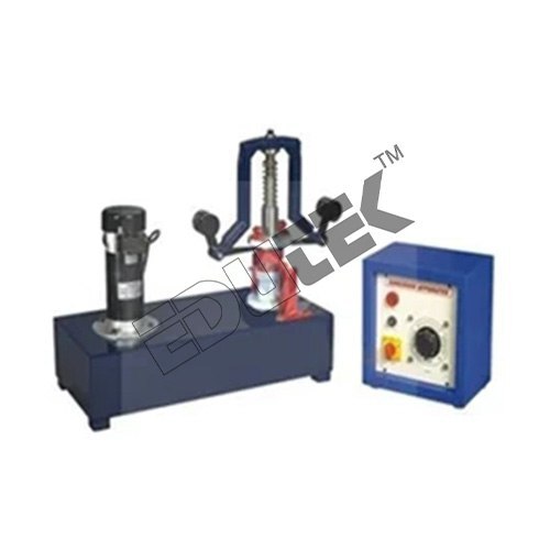
MOTORIZED GYROSCOPE APPARATUS
Price: 500 INR/Piece
Specification: MOTORIZED GYROSCOPE APPARATUS Manufacturing done in compliance with the set industry norms and guidelines, the offered Motorised Gyroscope Apparatus has its quality highly standardized. The finest raw materials and modern machines applied in its making, give the product superior performance and a longer service life. In addition, the offered range is marked at the most reasonable rate possible. We are a prominent firm engaged in offering Motorized Gyroscope Apparatus. The product is provided with a stainless steel disc mounted on a horizontal shaft. The variable speed motor of the product is mounted on a trunnion frame having bearings in a yoke frame which freely rotates about its vertical axis. To maintain a proper balance, the apparatus is installed with a weight pan on the other side of the rotor disc which can be moved about three axis. Scope of Experimentation Observation of gyroscopic effect of rotating disc To study the gyroscopic effect of a rotating disc Experimental justification of the equation T = l w. wp for calculating the gyroscopic couple by observation and measurement of results for independent vibrations in applied couple T and precession wp Utilities Required 1m x 1m, 230 V AC, single phase Bench area Tachometer to find out RPM of disc Electric supply Technical Details Stop Watch, Electronic Variable speed of standard make Supplied with Speed Control Unit Weights: 2 kg, 1 kg, kg Stainless Steel Diameter: 300 mm x 12 mm thick precisely balanced which can be rotated in 3 mutually perpendicular axis Motor Accurately marked scale & pointer to measure precession rate Features: Easy to operate Accurate Longer service life
 (ET-566J)
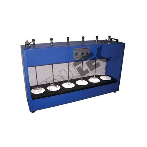
FLOCCULATION TEST RIG APPARATUS
Price: 500 INR/Piece
Specification: FLOCCULATION TEST RIG APPARATUS Product Description We have emerged as a well-known firm that is involved in offering an extensive range of Flocculation Jar Test Apparatus. Besides, we provide our valued patrons with the entire series at market leading prices. Features: Longer service life Advanced technology used Low maintenance Excellent in performance Compact design Longer working life Description: Uniform Stirring of up to 6 samples simultaneously. Variable Speed “ 20 “ 100 RPM Heavy Duty Motor Stainless Steel paddles with adjustable heights. Spacing of 6 between rod permit uses up to 1000 ml Beaker. Power- 220/230 V AC, Single Phase 50 Hz
 (ETE-2112)
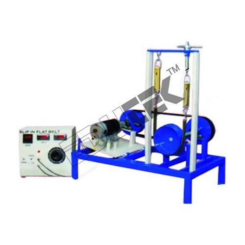
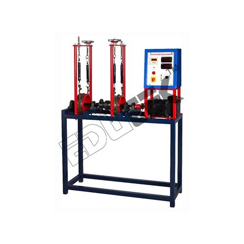
SLIP & CREEP MEASUREMENT APPARATUS
Price: 500 INR/Piece
Specification: SLIP & CREEP MEASUREMENT APPARATUS We are engaged in offering a wide array of Slip and Creep Measurement Apparatus for measure co-efficient of friction between pulley material and different belt materials. To measure belt slip speed and observe the limited value of load constant speed when the slip just starts. The motor speed is varied by Thyristor Control D.C. Drive. A double channel digital speed indicator indicates driving and driven pulley speeds. With the help of Stroboscope (not in the scope of supply) it is possible to demonstrate the slip of belt on driving and driven pulley. Used in major experimental applications, this range is inclusive of very salient features. Scope of Experimentation: To measure co-efficient of friction between pulley material and different belt materials To measure power transmitted with varied belt tension To measure percentage slip at fixed belt tension by varying load on the Brake drum and plot the graph of v/s percentage slip i.e. Slip Characteristics Finding a Creep Zone from graph To measure belt slip speed and observe the limiting value of load at constant speed when the slip just starts To study creep of belt Utilities Required: Electricity: 0.5 kW, 220 V, Single Phase Stroboscope Technical Details: Motor Variable speed DC Motor 1HP, 1500 RPM Pulleys Driving and driven pulleys of equal diameters (flat pulleys) Loading Arrangement Brake drum along with spring balance and rope arrangement is provided to load the system Belts Flat belts of fixed length of following belt material like Fabric Belt, Canvas Belt, Leather Belt Belt tightening arrangement Bearing block is sliding and dead weight can be applied to set the initial tension in belt Speed Indicator 2 Channel digital speed indicator with switch to change the channel
 (ET-5342)
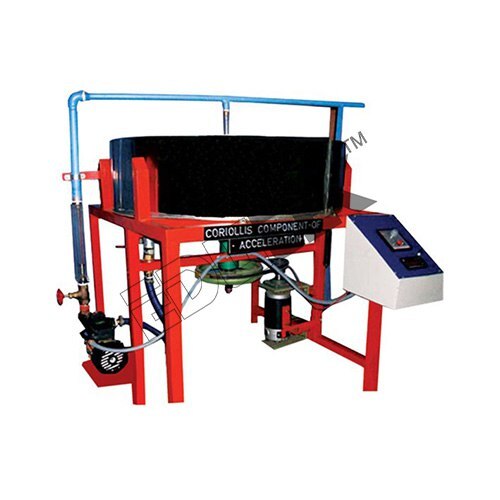
CORIOLLIS COMPONENT OF ACCELERATION APPARATUS
Price: 500 INR/Piece
Specification: CORIOLLIS COMPONENT OF ACCELERATION APPARATUS We are offering a wide range of Coriolis Component Acceleration. This entire set up is designed to study various coriollis components of a slider crank mechanism. In this process the continuous stream of water which is flowing through a steady rotating pair of tubes replaces mechanical slider system. The tubes of the system can be easily rotated in various speeds with the usage of a swinging field motor which also serves a dynamometer. There is a Perspex window located on the top of the tank. This window assures complete clear view of the process. It also prevents the splashing of water over the side of the tank. The in-built dynamometer continuously measures the torque which is applied to the various rotating tubes. This entire equipment is self-contained. The re-circulating of the water is assisted with a own speed control unit and water circulating pump which is separate. Experimentation To determine Coriolis Component of Acceleration at various speeds of rotation and water flow rates Utilities Required Electricity 0.5 kW, 220 V, Single Phase Drain Water Supply Technical Details: Swinging field type, variable speed Pump, FHP The whole set-up is well designed and arranged in a good quality painted structure Fabricated out of stainless steel Rotating arms 9mm/6mm orifice diameter, length 300 mm Rotameter, Electric motor, Main tank Control Panel comprises of: Speed control unit Standard make on/Off switch, mains indicator RPM indicator with proximity sensor RPM measurement
 (ET-5340)
UNIVERSAL GOVERNOR APPARATUS
Price: 500 INR/Piece
Specification: UNIVERSAL GOVERNOR APPARATUS We offer optimum quality Universal Governor Apparatus to our valuable customers. This universal governor apparatus offered by us is commonly used for studying the working of different governors that normally. The set-up is designed to study the working of different governors normally used to control the speed. It consists of a main spindle, mounted vertically on the base plate. This spindle is driven by a variable speed Motor which is also mounted vertically on the same base plate. Anyone governor assembly out of four can be mounted on spindle. Speed control unit controls the spindle speed. A graduated scale is fitted to the sleeve to measure the displacement. Experiments Determination of characteristic curve of a sleeve position against speed of rotation for all governors To study the effect of varying the mass of the center sleeve in Porter and Proell Governor To study the effect of varying the initial spring compression in Hartnell Governor To study the determination of characteristics curves of radius of rotation against controlling force (Actual & Theoretical) for all governors Utilities Required Power Supply: 230 V AC, Single Phase. Floor Space: 1.5 x 1.5 m Tachometer to find out RPM
 (ETCE-11964)
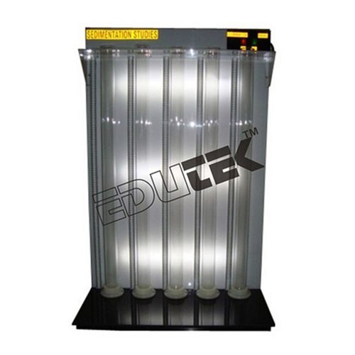
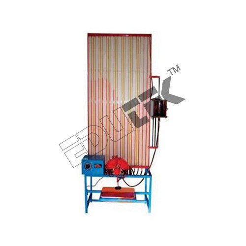
SEDIMENTATION STUDIES APPARATUS
Price: 500 INR/Piece
Specification: SEDIMENTATION STUDIES APPARATUS Our expertise in the field of manufacturing has helped us satisfy the expectations of our clients. The Sedimentation Studies are high quality equipment™s which are manufactured at our ultramodern infrastructure facility in compliance with the prevailing industrial standards. These are supplied to clients in different specifications at affordable market prices. Known for their sturdy designs and durable exterior, these equipment™s are highly demanded by chemical engineering laboratories. Descriptions of Sedimentation Studies Apparatus Settling or sedimentation is the separation of solid particles from fluids under the gravitational force. When a solid particle moves in a fluid. Then a number of forces are acting on it: o The gravitational force, acting downward. o The buoyant force, acting upward. o The drag force, acting upward. When a particle fall in a fluid under constant force, e.g. force of gravity, then particle accelerates for some time, but when the accelerating force equals the retarding force (Buoyant force and Drag force) then the resultant force acting on the particle will be zero, and particle quickly reaches velocity, which is the maximum attainable under the circumstances and which is called the terminal velocity. When slurry is prepared in a container and then allowed to remain undisturbed for some time, four settling zones will appear as below: A Supernatant Layer C Transition Zone B Slurry Zone D Concentration Sludge Zone. With the passage of time, the height of the different zones will vary and ultimately zone A of clear liquid and zone D of the sludge will be left. When all the solid particles settle in zone D, then this is critical stage and after this no settling takes place. With further passage of time, the height of the zone D will decrease due to the compression of the sludge on account of its own weight. Settling can be free settling or hindered settling. But most of the slurries settle under hindered conditions. Free settling is that in which the motion of one particle is unaffected by the motion of the other particle while in case of hindered settling many particles are present so there is mutual interference in the motion of the particles and the velocity of motion or rate of settling is reduced. The present set-up with 5 Nos. of Borosilicate Glass Graduated Cylinders is designed to study the zone settling depending upon the concentration and characteristics of the particles. These cylinders can be easily removed for cleaning. Rate of change in height of the various liquids/solids interfaces with respect to time can be measured with the help of stop watch. Experimentation of Sedimentation Studies Apparatus To determine Effect of initial concentration and initial suspension height on sedimentation rates. Effect of particle size distribution. Use of flocculating additives. Features: Reasonably priced Damage-resistant Efficient performance
 (ET-862Y)
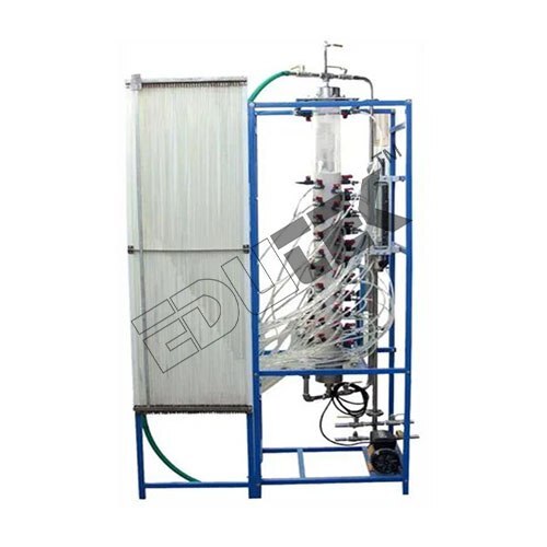
DEEP BED FILTER COLUMN APPARATUS
Price: 500 INR/Piece
Specification: DEEP BED FILTER COLUMN APPARATUS The present set-up is designed to study the characteristics of a filter column. It consists of a column filled with packing to ensure the good water distribution. 20 Slotted pressure tapings are mounted on the column for measuring the pressure drop across the bed per unit length. These tapings are connected to a differential manometer. These tapings can also be used for drawing the samples from the column and change in concentration of the suspension can be determined. The unit is complete with 2 Nos. of feed tanks. A centrifugal pump is provided to circulate the water through the column. Water supplied to the column is regulated and controlled by rotameter. Product Specification Water Circulation: FHP Pump Column Material: Stainless Steel/Perspex Column ID: 100 mm (approx.) Column Length: 1350 mm (approx.) Feed Tank Capacity: 200 Ltrs. (approx.) Flow Measurement: Rotameter for Water, 0.5 to 5 L/min. Pressure Tapings: 20 Nos. Sampling Ports: 20 Nos.
 (ET-721W)
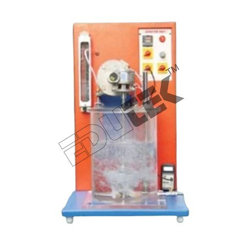
AERATION UNIT APPARATUS
Price: 500 INR/Piece
Specification: AERATION UNIT APPARATUS The set-up consists of an open water tank with variable speed paddle mixer. Air is supplied to the water from the bottom and mixed in the water by operating stirrer. Speed of the stirrer can be controlled with the help of speed controlled provided in the Panel. Flow of air entering in the water tank is directly metered with the help of Rotameter and can be regulated by means of Valve provided in the set-up. Three air diffusers of different types are provided with the set-up and are interchangeable. Desired diffuser can be easily installed on the air inlet to the water tank. A Temperature Indicator is also provided which gives the direct reading of water temperature. The present set-up is complete in all respect to demonstrate the oxygen transfer characteristics of diffused air system. A battery powered Dissolved Oxygen Meter accompanies the apparatus which allows to conduct the experiment with ease Product Specification Capacity: 25 ltr Type: NA Power: 220V AC 1 PHASE Application: LAB EXPERIMENT Country of Origin: Made in India
 (ET-781C)
PIN ON DISC WEAR APPARATUS
Price: 500 INR/Piece
Specification: PIN ON DISC WEAR APPARATUS Conforms to ASTM standards. Measurement of wear, friction, co-efficient of friction & temperature Performs test under sliding wear conditions. Real time data acquisition of wear, friction, co-efficient of friction & temperature etc. Product Specification Material: Stainless Steel Frequency: 50 Hz Country of Origin: Made in India
 (ET-5338)
JOURNAL BEARING APPARATUS
Price: 500 INR/Piece
Specification: JOURNAL BEARING APPARATUS The apparatus consists of a plain steel shaft excavated in a bearing and directly driven by a FHP Motor. The bearing is freely supported on the shaft and sealed at the motor end. The speed of the motor is controlled accurately by the speed control unit and it can be made run in both directions. Twelve equal-spaced pressure taping around the circumference and four along the axis are provided and are connected to manometer by PU Tubing so that the pressure head of oil in all tubes can be observed at a time. The bearing can be loaded by attaching weights to the arm supported beneath it. Experiments To study the pressure profile of lubricating oil at various conditions of load and speed Plotting the Cartesian polar pressure curves To measure the frictional torque and power transmit Utilities Required Electric supply: 230 V AC, Single Phase. Bench area: 1.5 x 1.5 x 4 m Tachometer to find out RPM of journal Oil SAE 40 about 5 Ltrs.
 (ET-579G)
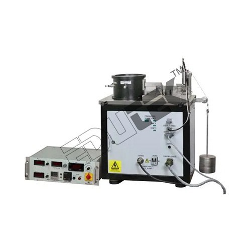
AEROBIC DIGESTER APPARATUS
Price: 500 INR/Piece
Specification: AEROBIC DIGESTER APPARATUS Aerobic Digester consists of a 2 gallon reactor vessel mounted on a steel base, with a liquid feed pump, air supply, and instrumentation for monitoring and controlling the process. The cylindrical wall of the reactor is made from 2 layers of porous plastic material to retain the suspended solids, while allowing treated water to pass through to the outer, annular exit chamber. This design allows the essential features of the aerobic treatment process to be studied without the distractions of having to settle the solids adequately enough for external recycle, a well-known laboratory problem. The porous liners are removable for cleaning, and a spare liner is supplied. Waste water is drawn from a feed tank by a 120V motor driven peristaltic pump. Flow rate is controlled by a variabe run time control that determines the minutes of run time within a 10 minute cycle. The pump delivers the feed to the reactor vessel through a transparent lid. Air is supplied at a measured rate by a small air pump, and discharges into the base of the reactor via an air distribution device. This provides the necessary oxygen for the digestion process, as well as produces sufficient bubbling for stirring and reaction. The liquid level in the reactor is maintained at a constant value of 1 or 2 gal. by an overflow device connected to the outer annular chamber of the vessel. Discharge is by gravity to a floor-standing product tank (not supplied). The reactor temperature is maintained by a 3-term PID controller which varies power to an immersion heater within the vessel. Any temperature between ambient and 95F may be selected, with the best conditions being a few degrees above the diurnal maximum in the user™s laboratory. Dissolved oxygen and pH probes and meters are included. The reactor lid contains a gas exit port, suitable for sampling the gases for subsequent analysis Feed pump 120V, peristaltic, 10 rpm, variable run time control corresponding to 0“13 gal. Per day Air pump 240V/120V, 0“1.35 gpm Reactor vessel 2 gal. maximum capacity pH meter Range 0.00 to 14.00 Dissolved oxygen meter Range 0“100% saturation, resolution 2%Reactor heater Electrical immersion 250WTemperature controller 3-term PID, temperature limit set at 95F
 (ET-262O)
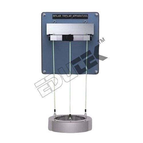
TRI-FILAR SUSPENSION SYSTEM
Price: 500 INR/Piece
Specification: TRI-FILAR SUSPENSION SYSTEM A uniform circular disc is suspended from the pendulum support frame by three parallel cords. Top ends of the cords pass through the three small chucks fitted at the top. Other ends are secured in the Tri-Filer disc. It is possible to adjust the length of the cord by loosening the chuck. Learning Objectives/Experiments: To determine the radius of gyration of tri-filar suspension. Required for Operation: Floor Area: 0.5 x 0.5 m. Technical Specifications: Circular disc: dia. 300 mm approx. Weights: 250 gms (3nos.), 750 gms (3 nos.) The whole set-up is ingeniously designed and schematically arranged on a powder-coated rigid structure
 (ET-637S)
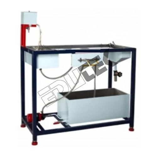
MODEL SEDIMENTATION TANK
Price: 500 INR/Piece
Specification: MODEL SEDIMENTATION TANK The apparatus is designed to demonstrate the hydraulic characteristics and settling efficiencies of a model settling basin. The apparatus consists of a Sedimentation Tank in which the water is fed by overhead tank (available in user laboratory and not in scope of supply) at constant flow rate and is measured with the help of a Rotameter. A complete unit for slurry circulation in sedimentation tank also accompanies the set-up including a sump tank for slurry, a feed pump for slurry. Flow rate of slurry entering the sedimentation tank is metered by suitable device. An accurate dye injection system is provided to inject the known volume of dye in the sedimentation tank. In sedimentation tank a weir is fitted which facilitate to the entry of well mixed slurry of known concentration in sedimentation tank uniformly. Product Specification Material: pvc/ss Type of Service Contract: Project Based Dimension: 6X4X5 FEET Usage/Application: LAB EXPERIMENT Current: 220V Cylinder: NA
 (ET-5346)
EPICYCLE GEAR TRAIN APPARATUS
Price: 500 INR/Piece
Specification: EPICYCLE GEAR TRAIN APPARATUS We are one of the leading manufacturers, suppliers, traders and exporters of optimum quality Epicyclic Gear Train Apparatus. This apparatus is manufactured from high quality raw material, which is procured from high known vendors. The quality controllers rigorously check the apparatus on the in-house quality check points Power Supply: 220 V AC, Single Phase Floor Area: 1.5 x 2 m Motor: Variable speed DC Motor, 1 HP
 (ET-340)
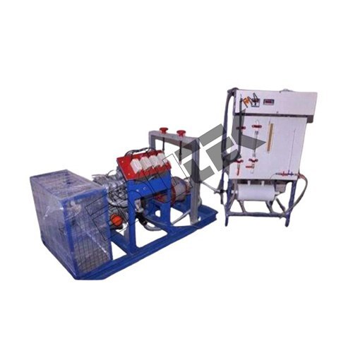
4 CYLINDER FOUR STROKE DIESEL ENGINE TEST RIG WITH ROPE BRAKE/ELECTRICAL BRAKE/HYDRAULIC BRAKE/AIR COOLED EDDY CURRENT/WATER COOLED EDDY CURRENT DYNAMOMETER
Price: 500 INR/Piece
Specification: 4 CYLINDER FOUR STROKE DIESEL ENGINE TEST RIG WITH ROPE BRAKE/ELECTRICAL BRAKE/HYDRAULIC BRAKE/AIR COOLED EDDY CURRENT/WATER COOLED EDDY CURRENT DYNAMOMETER IC engines are widely used in automobile, domestic and industrial sector. They are classified according to cycle, number of cylinders, arrangement of cylinders, fuel used, type of ignition, valve arrangement, cooling system. Test rigs are used to find out the performance of an IC engine. It consists of an IC Engine, dynamometer, fuel measuring, air intake measuring and various other arrangements.
 (ET-363)
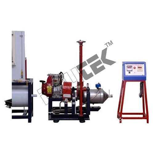
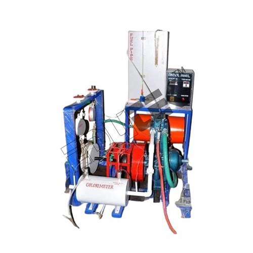
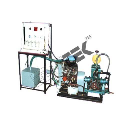
VCR 1 CYLINDER FOUR STROKE DUAL FUEL ENGINE TEST RIG WITH ROPE BRAKE/ELECTRICAL BRAKE/HYDRAULIC BRAKE/AIR COOLED EDDY CURRENT/WATER COOLED EDDY CURRENT DYNAMOMETER
Price: 500 INR/Piece
Specification: VCR 1 CYLINDER FOUR STROKE DUAL FUEL ENGINE TEST RIG WITH ROPE BRAKE/ELECTRICAL BRAKE/HYDRAULIC BRAKE/AIR COOLED EDDY CURRENT/WATER COOLED EDDY CURRENT DYNAMOMETER/COMPUTERIZED VCR 1 CYLINDER FOUR STROKE DUAL FUEL ENGINE TEST RIG. The setup consists of single cylinder, four stroke engine connected to dynamometer for loading. It is provided with necessary instruments for combustion pressure and crank angle measurements. These signals are interfaced to computer through engine indicator for P?-PV diagrams. Provision is also made for interfacing airflow, fuel flow, temperatures and load measurement. The setup has standalone panel box consisting of air box, fuel tank, manometer, fuel measuring unit, transmitters for air and fuel flow measurements, process indicator and engine indicator. Rotameters are provided for cooling water and calorimeter water flow measurement.
 (ET-419I)
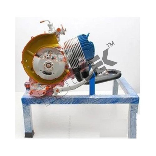
CUT SECTIONAL MODEL OF ACTUAL 1 CYLINDER 2 STROKE PETROL ENGINE
Price: 500 INR/Piece
Specification: CUT SECTIONAL MODEL OF ACTUAL 1 CYLINDER 2 STROKE PETROL ENGINE/CUT SECTIONAL MODEL OF ACTUAL 1 CYLINDER 4 STROKE PETROL ENGINE/CUT SECTIONAL MODEL OF ACTUAL 3 OR 4CYLINDER 4 STROKE PETROL ENGINE/CUT SECTIONAL MODEL OF ACTUAL 1 CYLINDER 4 STROKE DIESEL ENGINE/CUT SECTIONAL MODEL OF ACTUAL 4 CYLINDER 4 STROKE DIESEL ENGINE Cut Sectional Model Of Actual Single Cylinder Two Stroke Petrol Engine apparatus With Carburetor, spark plug etc. Complete with all salient parts sectioned for study of the various components and their function and to plot port-timing diagram on the single cylinder two-stroke petrol engine.
 (ET-339)
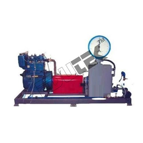
TWIN CYLINDER FOUR STROKE WATER COOLED DIESEL ENGINE TEST RIG WITH ROPE BRAKE/ELECTRICAL BRAKE/HYDRAULIC BRAKE/AIR COOLED EDDY CURRENT/WATER COOLED EDDY CURRENT DYNAMOMETER
Price: 500 INR/Piece
Specification: TWIN CYLINDER FOUR STROKE WATER COOLED DIESEL ENGINE TEST RIG WITH ROPE BRAKE/ELECTRICAL BRAKE/HYDRAULIC BRAKE/AIR COOLED EDDY CURRENT/WATER COOLED EDDY CURRENT DYNAMOMETER/COMPUTERIZED TWIN CYLINDER FOUR STROKE WATER COOLED DIESEL ENGINE TEST RIG. IC engines are widely used in automobile, domestic and industrial sector. They are classified according to cycle, number of cylinders, arrangement of cylinders, fuel used, type of ignition, valve arrangement, cooling system. Test rigs are used to find out the performance of an IC engine. It consists of an IC Engine, dynamometer, fuel measuring, air intake measuring and various other arrangements.
 (ET-638Y)
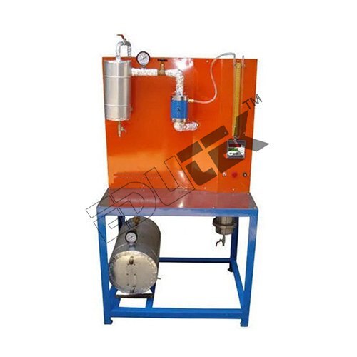
SEPARATING & THROTTLING CALORIMETER APPARATUS
Price: 500 INR/Piece
Specification: SEPARATING & THROTTLING CALORIMETER APPARATUS/ SEPARATING CALORIMETER APPARATUS/ THROTTLING CALORIMETER APPARATUS Description Separating Calorimeter: - It consists of two concentric chambers, the inner chamber and the outer chamber, which communicates with each other through an opening at the top. As the steam discharges through the metal basket, which has a large number of holes, the water particles due to their heavier momentum get separated from the steam and collect in the chamber. The comparatively dry steam in the inner chamber moves up and then down aging through the annular space between the two chambers and enters the Throttling Calorimeter. Throttling Calorimeter: - It consists a narrow throat (Orifice). Pressure and temperature are measured by pressure gauge and thermometer. The steam after throttling process passes through the heat exchanger and condensate is collected. Steam Generator is also provided to supply the saturated steam (Max.) at 2kg/cm2 pressure. Experimentation/Learning Objectives To find the dryness fraction of steam. Utilities Required Electric Supply: Single Phase, 220 V, 10 Amp. Continuous Water Supply: 10 LPM Approx. at kg/cm2 pressure Technical Details Separating Chamber: Compatible capacity made of Stainless Steel insulated with Ceramic wool with water level indicator. Throttling Chamber: Compatible capacity provided with gauge to measure inlet Pressure before throttling Heat Exchanger: For Condensing steam after throttling chamber Steam Generator: Compatible capacity with digital temperature controller to control the temperature inside the steam generator. Differential pressure: By manometer Measurement Steam pressure measurement: By Pressure gauge
 (ET-5333)
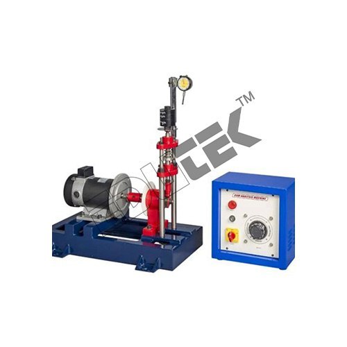
CAM ANALYSIS APPARATUS
Price: 500 INR/Piece
Specification: CAM ANALYSIS APPARATUS Edutek We are engaged in providing superior quality Cam Analysis Apparatus to our most reliable clients. These Cam Analysis Apparatus are appreciated by large number of clients due to high quality and durability. These products are available in market at most competitive rates. Descriptions Apparatus is a motorized unit consisting of a camshaft driven by a variable speed motor. The shaft runs in a double bearing. The free end of the camshaft has a facility to mount the cam easily. The follower is properly guided in gunmetal bushes and the type of follower can be changed according to the cam under test. Graduated circular protractor is fitted co-axial with the shaft. And a Dial Gauge fitted on the follower shaft is used to note the follower displacement for the angle of cam rotation. A spring is used to provide controlling force to the follower system. Weights on the follower shaft can be adjusted as per the requirement. An arrangement is provided to regulate the speed. The apparatus is very useful- for testing the cam performance for jump phenomenon during operation. On this apparatus the effect of change of inertia forces on jump action of earn-follower during operation can be observed. It is useful for testing various cam & follower pairs. Three cams and three followers will be supplied with the apparatus. These are already hardened to reduce the wear. Experiments With the help of combination of provided cams and followers following experiments can be conducted: To plot the n-Q (Follower displacement Vs Angle of rotation) curves for different cam follower pairs The follower bounce can be observed by using a stroboscope (Optional) & effect of follower weight on bounce can be studied. To study the effect of follower weight on bounce To study the effect of spring compression on bounce The tests can be repeated by changing compression springs, follower weights and cam speed. Utilities Required Electricity 0.5 kW, 220 V, Single Phase Stroboscope (Optional)
 (ET-341)
VCR 1 CYLINDER FOUR STROKE DIESEL ENGINE TEST RIG WITH ROPE BRAKE/ELECTRICAL BRAKE/HYDRAULIC BRAKE/AIR COOLED EDDY CURRENT/WATER COOLED EDDY CURRENT DYNAMOMETER
Price: 500 INR/Piece
Specification: VCR 1 CYLINDER FOUR STROKE DIESEL ENGINE TEST RIG WITH ROPE BRAKE/ELECTRICAL BRAKE/HYDRAULIC BRAKE/AIR COOLED EDDY CURRENT/WATER COOLED EDDY CURRENT DYNAMOMETER/COMPUTERIZED VCR 1 CYLINDER FOUR STROKE DIESEL ENGINE TEST RIG. IC engines are widely used in automobile, domestic and industrial sector. They are classified according to cycle, number of cylinders, arrangement of cylinders, fuel used, type of ignition, valve arrangement, cooling system. Test rigs are used to find out the performance of an IC engine. It consists of an IC Engine, dynamometer, fuel measuring, air intake measuring and various other arrangements.
 (ET-5332)
UNIVERSAL VIBRATION APPARATUS
Price: 500 INR/Piece
Specification: UNIVERSAL VIBRATION APPARATUS We are engaged in the manufacturing and exporting of Universal Vibration Apparatus. To verify the relation of compound pendulum & to determine the radius of gyration. To study the forced vibration of simply supported beam for different damping. Descriptions The Universal Vibration apparatus provided comprehensive unit to perform the vibration experiments. A universal frame is provided upon which quick and easy assembly of various experiments can be done. The unit is self-contained to safely store spares. The students can easily assemble the experiments and study the theory of vibrations practically. Experimentation Following experiments can be performed with this unit: To verify the relation simple pendulum. To verify the relation of compound pendulum & to determine the radius of gyration. To study radius of gyration of bifilar suspension. To study the undamped free vibration of spring mass system. To study the longitudinal vibration of helical coiled spring. To study the damped torsional vibration of single rotor system and to determine the damping co-efficient. To study the forced vibration of simply supported beam for different damping. Undamped torsional vibrations of single rotor system. Undamped torsional vibrations of double rotor system. Verification of Dunker leys Rule.
 (ET-342)
1 CYLINDER FOUR STROKE DUAL FUEL ENGINE TEST RIG WITH ROPE BRAKE/ELECTRICAL BRAKE/HYDRAULIC BRAKE/AIR COOLED EDDY CURRENT/WATER COOLED EDDY CURRENT DYNAMOMETER
Price: 500 INR/Piece
Specification: 1 CYLINDER FOUR STROKE DUAL FUEL ENGINE TEST RIG WITH ROPE BRAKE/ELECTRICAL BRAKE/HYDRAULIC BRAKE/AIR COOLED EDDY CURRENT/WATER COOLED EDDY CURRENT DYNAMOMETER The setup consists of single cylinder, four stroke engine connected to dynamometer for loading. It is provided with necessary instruments for combustion pressure and crank angle measurements. These signals are interfaced to computer through engine indicator for P?-PV diagrams. Provision is also made for interfacing airflow, fuel flow, temperatures and load measurement. The setup has standalone panel box consisting of air box, fuel tank, manometer, fuel measuring unit, transmitters for air and fuel flow measurements, process indicator and engine indicator. Rotameters are provided for cooling water and calorimeter water flow measurement.
 (ETE-2114)
STATIC & DYNAMIC BALANCING DEMONSTRATION
Price: 500 INR/Piece
Specification: STATIC & DYNAMIC BALANCING DEMONSTRATION This equipment is designed for carrying out the experiment for balancing a rotation mass system. The apparatus consists of a steel shaft fixed in a rectangular frame. A set of four blocks with a clamping arrangement is provided. For static balancing, each block is individually clamped on shaft and its relative weight is found out using cord and container system in terms of number of steel balls. For dynamic balancing, a moment polygon is drawn using relative weights and angular and axial position of blocks is determined. The block is clamped on shaft is rotated by a motor to check dynamic balance of the system. The system is provided with angular and longitudinal scales and is suspended with chains for dynamic balancing. Experiments To balance the masses statically and dynamically of a single rotating mass system To observation of effect of unbalance in a rotating mass system Utilities Required Electricity 0.5kW, 220V, Single Phase
 (ET-5334)
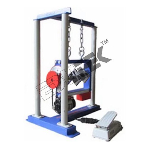
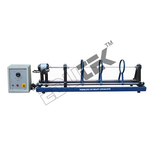
WHILING OF SHAFT DEMONSTRATION
Price: 500 INR/Piece
Specification: WHILING OF SHAFT DEMONSTRATION The setup is designed to study the whirling of shafts. The set-up consists of a sturdy M.S. frame, variable speed motor bearing holders etc. Different bearing can be fitted in bearing block to have different end conditions i.e. (i) both end fixed, (ii) one end free and one end fixed etc. A variable speed motor is provided to drive the shaft along with speed control unit as the test is destructive, hence the shaft cannot be used again. Experiments Display of various modes of whril for a shaft with: Both ends directionally fixed. One ends fixed and other free Both ends directionally free. Modes of vibrations can be studied and frequency can be measured in each case. Utilities Required Floor area of 2m x 0.5 m Electric supply of 230V, AC
 (ET-752V)
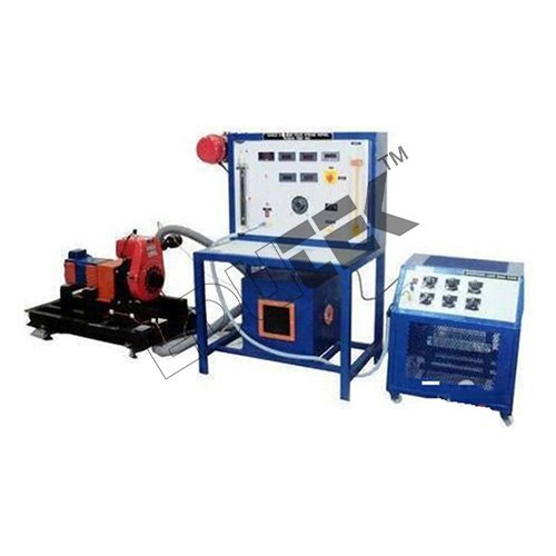
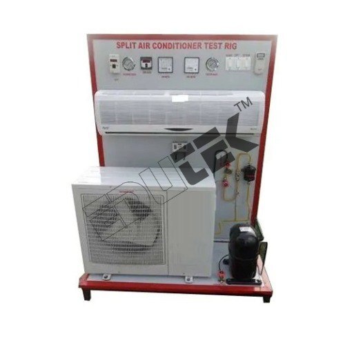
SPLIT AIR CONDITIONER TEST RIG
Price: 500 INR/Piece
Specification: SPLIT AIR CONDITIONER TEST RIG Phase: Single Phase Voltage: 220V Material: Mild Steel Power: 1.25 KW Temperature Sensor: RTD PT-a hundred Kind Compressor: 1HP Current: 10 Amp
 (ET-811Z)
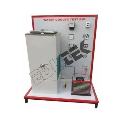
WATER COOLER TEST RIG
Price: 500 INR/Piece
Specification: WATER COOLER TEST RIG We are engaged in the manufacturing, trading and exporting of superior quality Water Cooler Test Rig at a nominal market price. These products are manufactured under proper guidance using latest technology, advanced machinery and quality tested raw materials. Offered lab equipment is appreciated for their seamless finish, optimum performance and longer functional life. Cooling tower material: M.S. sheets Size: 200 X 200 mm. Height: 1.2m Water Heater power: 3 Kw capacity to provide hot water Centrifugal blower power: 1 HP to force air through tower Multichannel Digital Temperature Indicator to measure temperature at various points Rotameter to measure inlet water flow Measuring tank to measure outlet water flow Calibrated orifice and water manometer to measure air flow Arrangement to measure temperatures of water at five intermediate stations along the height of tower
 (ET-181Q)
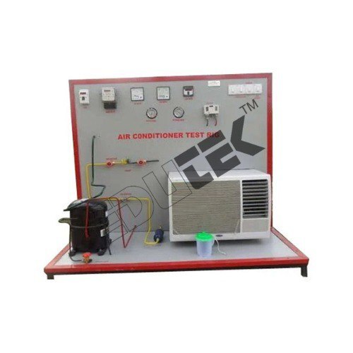
AIR CONDITIONER TEST RIG
Price: 500 INR/Piece
Specification: AIR CONDITIONER TEST RIG We offer exclusive quality Air Conditioning Trainer at the most affordable market price. These trainers are manufactured under the supervision of expert professionals using latest technology and quality tested raw materials. Appreciated for their hassle-free installation, sturdy construction, corrosion resistance and longer functional life, offered trainers are widely demanded by the clients. Specifications To study the vapor compression AC cycle To calculate COP To evaluate the tonnage capacity of the air conditioning system by enthalpy difference method. To evaluate actual and theoretical C.O.P. of the system. To plot the refrigeration cycle on P-H & T-S charts. To plot the psychometric processes on psychometric charts. To study the vapor compression AC cycle To calculate COP Utilities Required Stabilized power supply 15 Amp 220 V AC
 (ET-916P)
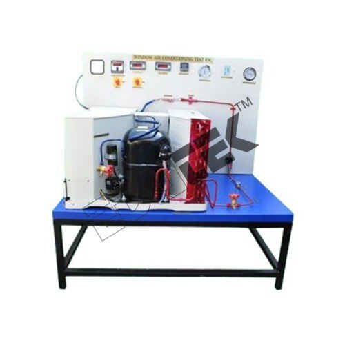
WINDOW AIR CONDITIONER TEST RIG
Price: 500 INR/Piece
Specification: WINDOW AIR CONDITIONER TEST RIG The model will be suitably sectioned to demonstrate the internal construction details showing the minute information, and working of the same, the model will be suitably painted and mounted on a metal or wooden base & supplied with key card & very interesting literature regarding working of the same. EXPERIMENTAL SETUP Compressor: Hermetically sealed compressor. Condenser: Air Cooled condenser made out of copper pipe & Aluminum fins of matching capacity with fan cooling. Evaporator: Fins and Copper tube type cooling coil of suitable capacity fitted in the unit Best Indian make. Expansion device: Thermostatic expansion valve. Energy Meter: For power measurement of compressor. Pressure Gauge: 2 Nos. for H.P., L.P. measurement Suitable filter/drier. Hand Shut Off type Service valve. Rotameter for Refrigerant flow measurement. MS Stand: The unit shall be assembled on heavy duty Angle Iron Base. Voltage: Single Phase 220 Volts 50 Hz. Ac Supply. Manual: Operation and maintenances manual should be provided along with the supplied equipment
 (ET-499B)
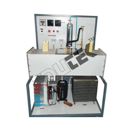
AIR WASHER TEST RIG
Price: 500 INR/Piece
Specification: AIR WASHER TEST RIG Air Washer Test Rig unit is required to conduct experiments and demonstrate the basic principal of psychometric properties of air. The test rig is designed for study of humidification of air. The unit is provided with all instruments and facilities to measure the temperature wherever required. The setup also provides the facility to conduct the experiment of heating and cooling of air and humidification. Experimentation/learning objectives: To study the cooling, humidification & dehumidification of air. To calculate the change in specific humidity of air. To calculate the change in temperature of air Utilities required: Electric supply: Single Phase, 220 V AC, 50 Hz. 32 Amp. MCB with earth connection. Earth voltage should be less than 5 volts. Water Supply: Initial fill. Floor Drain Required. Floor Area: 4.0 m x 1.5 m
 (ET-336)
3 OR 4 CYLINDER FOUR STROKE PETROL ENGINE TEST RIG WITH ROPE BRAKE/ ELECTRICAL BRAKE/HYDRAULIC BRAKE/ AIR COOLED EDDY CURRENT/WATER COOLED EDDY CURRENT DYNAMOMETER
Price: 500 INR/Piece
Specification: 3 OR 4 CYLINDER FOUR STROKE PETROL ENGINE TEST RIG WITH ROPE BRAKE/COMPUTERIZED 3 OR 4 CYLINDER FOUR STROKE PETROL ENGINE TEST RIG. Engine “ Automotive petrol engine. Four stroke four cylinder, water cooled, developing 20 BHP at 3000 RPM, provided with battery and self-starter. Rope Brake Dynamometer. OR suitable capacity hydraulic dynamometer also we can provide with electrical dynamometer. Measurements provided “ o Fuel intake measurement. o Air intake measurement. o Water circulated through engine jacket. o Water circulated exhaust gas calorimeter. o Digital Temperature Indicator for Exhaust gas & water temperature o Tachometer o Gauges for oil pressure & battery condition. o Arrangement to cut off the ignition to conduct morse test the test rig enables to determine I.H.P. B.H.P., specific fuel consumption, Air fuel ratio volumetric efficiency and heat balance sheet at different loads and speeds. A technical manual accompanies the unit.
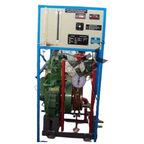 (ET-338)
1 CYLINDER FOUR STROKE WATER COOLED DIESEL ENGINE TEST RIG WITH ROPE BRAKE/ELECTRICAL BRAKE/HYDRAULIC BRAKE/AIR COOLED EDDY CURRENT/WATER COOLED EDDY CURRENT DYNAMOMETER
Price: 500 INR/Piece
Specification: 1 CYLINDER FOUR STROKE WATER COOLED DIESEL ENGINE TEST RIG WITH ROPE BRAKE/ELECTRICAL BRAKE/HYDRAULIC BRAKE/AIR COOLED EDDY CURRENT/WATER COOLED EDDY CURRENT DYNAMOMETER/COMPUTERIZED 1 CYLINDER FOUR STROKE WATER COOLED DIESEL ENGINE TEST RIG. Description: The Test Rig consists of a vertical single cylinder water cooled compression ignition type diesel engine. It is coupled to a loading dynamometer, which in this case is Rope Brake Dynamometer. All the components are mounted on heavy duty M S channel. A desk type control panel consists of the following instrumentation: Digital RPM Indicator to measure the speed of the engine. Digital temperature indicator to measure various temperatures. Differential manometer to measure quantity of air sucked into cylinder. Burette with manifold to measure the rate of fuel consumed during test
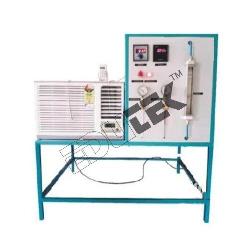 (ET-756U)
AIR COOLER TEST RIG
Price: 500 INR/Piece
Specification: AIR COOLER TEST RIG Air Cooler Test Rig unit is required to conduct experiments and demonstrate the basic principal of psychometric properties of air. The test rig is designed for study of cooling of air. The unit is provided with all instruments and facilities to measure the temperature wherever required. The setup provides the facility to conduct the experiment of cooling of air by temperature measurements.
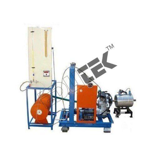 (ET-334)
1 CYLINDER TWO STROKE PETROL ENGINE TEST RIG WITH ROPE BRAKE/ ELECTRICAL BRAKE/HYDRAULIC BRAKE/ AIR COOLED EDDY CURRENT/WATER COOLED EDDY CURRENT DYNAMOMETER
Price: 500 INR/Piece
Specification: 1 CYLINDER TWO STROKE PETROL ENGINE TEST RIG WITH ROPE BRAKE/ ELECTRICAL BRAKE/HYDRAULIC BRAKE/ AIR COOLED EDDY CURRENT/WATER COOLED EDDY CURRENT DYNAMOMETER// COMPUTERIZED 1 CYLINDER TWO STROKE PETROL ENGINE TEST RIG. Ic Engines Are Widely Used in Automobile, Domestic and Industrial Sector. They Are Classified According to Cycle, Number of Cylinders, Arrangement of Cylinders, Fuel Used, Type Of Ignition, Valve Arrangement, Cooling System. Test Rigs Are Used To Find Out The Performance Of An Ic Engine. It Consists of An Ic Engine, Dynamometer, Fuel Measuring, Air Intake Measuring And Various Other Arrangements.
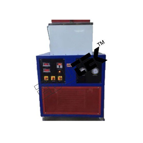 (ET-934B)
VAPOUR COMPRESSION CYCLE TRAINER APPARATUS
Price: 500 INR/Piece
Specification: VAPOUR COMPRESSION CYCLE TRAINER APPARATUS The set up demonstrates the students about the basic principal of a refrigeration cycle. The test rig is designed for the study of thermodynamics of vapour Compression refrigeration cycle by way of demonstration and experimentation. It has a facility to measure various parameters for experimentation. Object:- To Study the Vapour Compression refrigerator cycle. To Calculate Co-efficient of performance Utilities required Electric supply: Single phase, 220 V AC, 50 Hz, 5-15 amp combined socket with earth connection. Earth voltage should be less than 5 volts. Water supply: 2LPM@1bar Floor drain required. Floor area: 1.5 m x 1 Technical detail: Compressor: Hermitically sealed compressor, reciprocating type. Capacity 1/3 Ton, Emerson Copeland make. Refrigerant: R-134-A Agitator: Compatible capacity. Condenser: Air cooled compatible to compressor Condenser Cooling Fan: Compatible capacity with permanent lubricated motor. Evaporator: Made of Stainless Steel, Insulated with ceramic wool/P.U.F. Rotameter: Make: Eureka, Range (6-60) LPH Expansion Device: Capillary Tube, Compatible Capacity. Pressure Gauges: 2 Nos. (For suction & discharge pressure) Safety Control: Overload and over current protectors for compressor and Time delay circuit with Low/high voltage auto-cut. Temperature Sensor: RTD PT-100 Type Control Panel comprises of: Digital Voltmeter: 0-500 V Digital Ammeter: 0-19.99Amp. Temperature Measurement: Digital Temperature Indicator with multi-channel switch. With mains indicator, Standard make On-off switch etc.
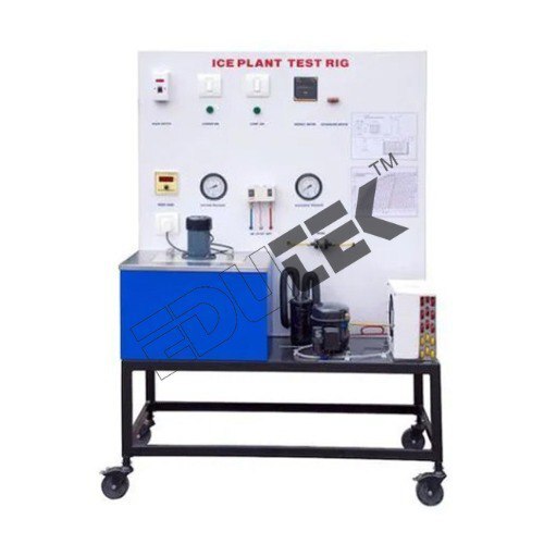 (ET-347D)
ICE PLANT TEST RIG
Price: 500 INR/Piece
Specification: ICE PLANT TEST RIG Description The unit enables the students to study the Basic Principals of ice plant cycle within a short period. The test rig is designed for the study of thermodynamics of vapour Compression refrigeration cycle by way of demonstration and experimentation. It has a facility to measure various parameters for experimentation. Ice cans are kept in liquid tank, which is cooled by the refrigerant evaporator. As conventional ice plants take 12-24 hours to complete the cycle, this ice plant is specially designed to demonstrate process of ice formation to be complete within period of 4 hours and hence it is most suitable for laboratory use. Experimentation To study the working of Ice Plant. To Study the refrigerator circuit. To Calculate Co-efficient of performance Utilities Required Electric supply: Single Phase, 220V AC, 50 Hz, 10 Amp with earth connection. Water supply and drainage Floor area: 1.5 m x 1m Ethyl Glycolet: 25 Ltr.
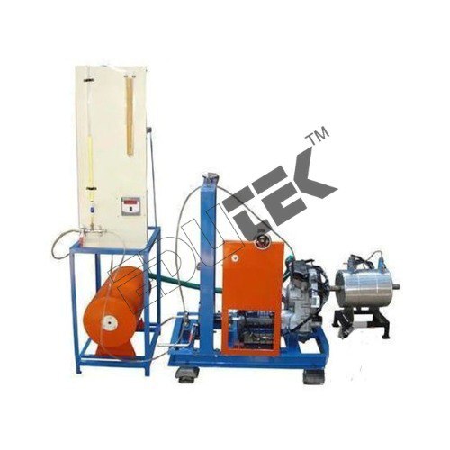 (ET-337)
VCR 1 CYLINDER FOUR STROKE PETROL ENGINE TEST RIG WITH ROPE BRAKE/ELECTRICAL BRAKE/HYDRAULIC BRAKE/AIR COOLED EDDY CURRENT/WATER COOLED EDDY CURRENT DYNAMOMETER
Price: 500 INR/Piece
Specification: VCR 1 CYLINDER FOUR STROKE PETROL ENGINE TEST RIG WITH ROPE BRAKE/ELECTRICAL BRAKE/HYDRAULIC BRAKE/AIR COOLED EDDY CURRENT/WATER COOLED EDDY CURRENT DYNAMOMETER/COMPUTERIZED VCR 1 CYLINDER FOUR STROKE PETROL ENGINE TEST RIG. IC engines are widely used in automobile, domestic and industrial sector. They are classified according to cycle, number of cylinders, arrangement of cylinders, fuel used, type of ignition, valve arrangement, cooling system. Test rigs are used to find out the performance of an IC engine. It consists of an IC Engine, dynamometer, fuel measuring, air intake measuring and various other arrangements.
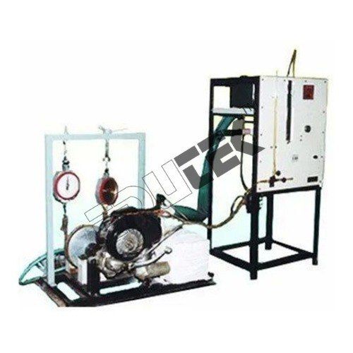 (ET-335)
1 CYLINDER FOUR STROKE PETROL ENGINE TEST RIG WITH ROPE BRAKE/ ELECTRICAL BRAKE/HYDRAULIC BRAKE/ AIR COOLED EDDY CURRENT/WATER COOLED EDDY CURRENT DYNAMOMETER
Price: 500 INR/Piece
Specification: 1 CYLINDER FOUR STROKE PETROL ENGINE TEST RIG WITH ROPE BRAKE/ ELECTRICAL BRAKE/HYDRAULIC BRAKE/ AIR COOLED EDDY CURRENT/WATER COOLED EDDY CURRENT DYNAMOMETER/COMPUTERIZED 1 CYLINDER FOUR STROKE PETROL ENGINE TEST RIG. It is provided with necessary equipment and instruments for combustion pressure and crank-angle measurements. The set-up also consists of air intake measuring unit, fuel measuring unit, temperature measuring unit and an exhaust gas calorimeter. The setup enables study of engine performance for brake power, indicated power, frictional power, BMEP, IMEP, brake thermal efficiency, indicated thermal efficiency, Mechanical efficiency, volumetric efficiency, specific fuel consumption, A/F ratio and heat balance. Rotameter are provided for cooling water and calorimeter water flow measurement.
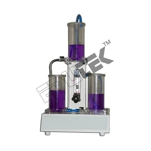 (EDPC-9113)
INTERACTING & NON INTERACTING SYSTEM APPARATUS
Price: 500 INR/Piece
Specification: INTERACTING & NON-INTERACTING SYSTEM APPARATUS The setup is designed to study dynamic response of single and multi-capacity processes when connected in interacting and non-interacting mode. It is combined unit to study Single capacity process, Non-interacting process and Interacting process. The observed step response of the tank level in different mode can be compared with mathematically predicted response. Setup consists of supply tank, pump for water circulation, Rotameter for flow measurement, process tanks with scales, which can be connected to interacting and no interacting mode. The components are assembled on frame & base plate. Experimentation/Learning Objectives Dynamics study for Step response Single capacity Tank Interacting mode Non-Interacting mode Utilities Required Electric supply: Single Phase, 220 V AC, 5-15-amp combined socket with earth connection. Earth voltage should be less than 5 volts. Water supply Floor Drain Floor area: 1.0 m x 1.0 m Technical Details Process Tank: Material Stainless Steel, Circular, with graduated level scale (3 Nos.) Capacity 3.5 liters each (approx.) Supply Tank: Material Stainless steel, Capacity 20 litres. Overhead tank: Material Stainless steel, Capacity 5 litres. Water Circulation: FHP Pump, Champion/Standard make. Piping: SS & PVC, size ¼ Flow Measurement: By Rotameter. The whole unit is assembled rigidly on a base plate.
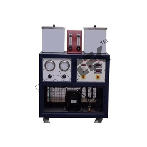 (ET-435Q)
WATER TO AIR HEAT PUMP APPARATUS
Price: 500 INR/Piece
Specification: WATER TO AIR HEAT PUMP APPARATUS Heat Pump and the refrigerating machine basically work on one and the same principle and with the same components. Heat pump is a machine, which delivers heat at a temperature suitable for domestic, Industrial and Commercial purposes. By added work input from the motor or engine it extracts heat from low-grade source. In many circumstances heat pumps can make valuable contribution to energy conservation. The majority of heat pumps operate on the vapour compression cycle using a refrigerant as the working fluid. Heat pump is fully sealed R-134A refrigerant system using water-to-water pumping principle. The equipment produces realistic results and has low thermal inertia so that unit stabilises very quickly and enables student™s maximum experimentation.
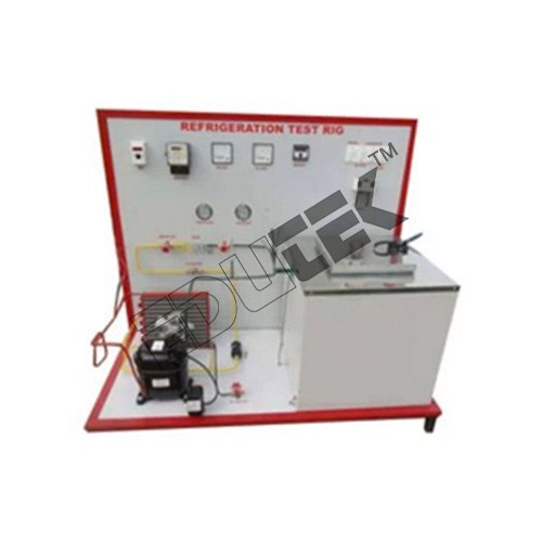 (ET-522F)
REFRIGERATION TEST RIG
Price: 500 INR/Piece
Specification: REFRIGERATION TEST RIG Edutek is one of the leading manufacturer and exporter of engineering lab Equipment. Refrigeration Test Rig The set up demonstrates the students about the basic principal of a refrigeration cycle. The test rig is designed for the study of thermodynamics of vapour Compression refrigeration cycle by way of demonstration and experimentation. It has a facility to measure various parameters for experimentation. Description: The set up demonstrates the students about the basic principal of a refrigeration cycle. The test rig is designed for the study of thermodynamics of vapour Compression refrigeration cycle by way of demonstration and experimentation. It has a facility to measure various parameters for experimentation. Experimentation: To calculate refrigerant capacity. To Study the Vapour Compression refrigerator cycle. To Calculate Co-efficient of performance and draw P-H Diagram. Utilities Required: Electric supply 5A-220 V AC Water supply and drainage Floor area: 1.5 m x 1m Technical Details: Compressor: Hermitically sealed compressor. Capacity: 1/3 Ton, Kirloskar make. Agitator: Compatible capacity. Condenser: Air cooled compatible to 1/3 Ton compressor Condenser cooling fan: Compatible capacity with permanent lubricated motor. Evaporator: Made of Stainless Steel, Insulated with ceramic wool/P.U.F. Rotameter: Range 6 to 60 LPH Expansion Device: Capillary Tube, Compatible Capacity. Pressure Gauges: 2 Nos. Safety Control: overload and over current protectors for compressor and Time delay circuit. Temperature Sensor: RTD PT-100 Type. Control Panel comprises of: Digital Voltmeter: 0-300 V
 (ET-766B)
AIR TO AIR HEAT PUMP APPARATUS
Price: 500 INR/Piece
Specification: AIR TO AIR HEAT PUMP APPARATUS Heat Pump and the refrigerating machine basically work on one and the same principle and with the same components. Heat pump is a machine, which delivers heat at a temperature suitable for domestic, Industrial and Commercial purposes. By added work input from the motor or engine it extracts heat from low-grade source. In many circumstances heat pumps can make valuable contribution to energy conservation. The majority of heat pumps operate on the vapour compression cycle using a refrigerant as the working fluid. Heat pump is fully sealed R-134 A refrigerant system using water-to-water pumping principle. The equipment produces realistic results and has low thermal inertia so that unit stabilizes very quickly and enables student™s maximum experimentation.
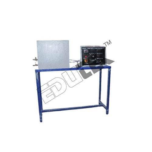 (ET-218N)
FORCE MEASUREMENT APPARATUS
Price: 500 INR/Piece
Specification: FORCE MEASUREMENT APPARATUS Description: Present set up consist of load cell fitted with the dead weight tray. Weight can be applied manually on the tray and output is displayed in the panel. Experimentation/learning objectives: To study the working of Load Cell. Utilities required: Electric supply: Single Phase, 220 V AC, 5-15 amp combined socket with earth connection. Earth voltage should be less than 5 volts. Table for set-up support Technical details: Load cell: 50 Kg. Load Indicator: For Digital Display of Load cell Output Weight Set: 10 Kg x 3 Nos., 5 Kg x 3 Nos. & 1 Kg. x 5 Nos.
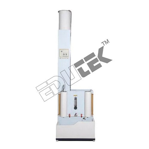 (ET-738T)
TWO TANK NON-INTERACTING SYSTEM APPARATUS
Price: 500 INR/Piece
Specification: TWO TANK NON-INTERACTING SYSTEM APPARATUS Description: The setup studies behavior of multi capacity process when connected in non-interaction mode. It consists of supply tank, pump for water circulation, Rotameter for flow measurement, two independent process tanks with scales connected in non-interacting mode. The components are assembled on frame to form tabletop set-up. Experimentation: To obtain experimentally the step response and to compare the experimental and theoretical responses Product Specifications Material: Metal Usage: Laboratory Equipment Materials: PU Type: Non-Interacting Temperature Range: 35 Celsius (degree C)
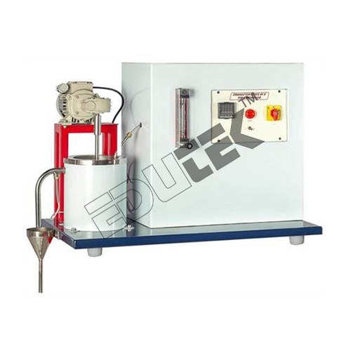 (ET-839T)
CHARACTERISTICS OF P.I.D. CONTROLLER APPARATUS
Price: 500 INR/Piece
Specification: CHARACTERISTICS OF P.I.D. CONTROLLER APPARATUS Description: The present set-up is designed to study the characteristics of a PID controller. It consists of a stirred tank in which a heater is provided to heat the water. Water is supplied to the tank from laboratory overhead tank by the user. The flow rate can be adjusted by operating the needle valves provided on Rotameter. PID parameters can be changed for conducting experiment on P, PI, PD and PID mode. Controller can be operated on Auto Tune mode in which controller automatically fixes the value of P, I and D. Temperature is sensed by the PID Controller and the controller gives input to the heater, accordingly. Experiment can be performed on various flow rates and temperature set points. Experimentation: To study the behaviour of a PID controller. Product Specifications Usage: Laboratory Material: Metal Voltage: 220 Volt (v) Equipment Materials: Brass Type: Controller Temperature Range: 60 Celsius (oC) Display Type: Digital
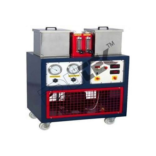 (ET-140Z)
WATER TO WATER HEAT PUMP APPARATUS
Price: 500 INR/Piece
Specification: WATER TO WATER HEAT PUMP APPARATUS Features: Low maintenance Easy to use Fine finish Experimentation: Determination of co-efficient of performance of the unit when working as water-to-water heat pump To construction of energy balances for completed system over a range of operating conditions To determine overall heat transfer co-efficient for condenser and evaporator Technical Detail: Condenser: Water Cooled Type Shell and Coil Condenser with Refrigerant inside The Tube Water Flow Measurement: Provided with Individual Rota Meters And Four Temperature Sensor for Both Condenser and Evaporator Expansion Valve: Capillary Tube, Compatible Capacity Safety Control: Overload and Over Current Protectors for Compressor and Time Delay Circuit Temperature Measurement: Digital Temperature Indicator with Multi-Channel Switch Instruction Manual: An English instruction manual will be Provided Along with the Apparatus All the accessories will be mounted on a rigid base frame made of M.S. and it will be powder coated
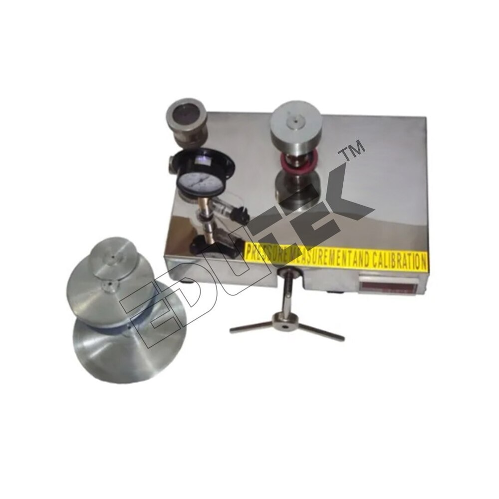 (ET-11957D)
DEAD WEIGHT PRESSURE GAUGE TESTER APPARATUS
Price: 500 INR/Piece
Specification: DEAD WEIGHT PRESSURE GAUGE TESTER APPARATUS Deadweight testers are the basic primary standard used worldwide for the accurate calibration of pressure gauges, pressure transducers etc. The equipment is self-contained and portable so it may be used in lecture theatre demonstrations or as a master calibrator for the laboratory. The instrument combines a low and high-pressure range provided by two pistons of different effective area. Calibration is accurate to within ±0.025% of reading. A laboratory calibration certificate is supplied for each piston together with a traceable certificate of overall accuracy. The pressure in the system is produced by means of a capstan-operated hydraulic ram balanced by deadweight acting upon a piston of known area. Oil is used as the hydraulic fluid. The pressure developed is applied to the gauge that is to be calibrated. A spirit level and adjustable feet are provided to enable the operator to level the instrument. A flotation indicator mounted on the top plate removes the guesswork when floating the piston. The instrument is supplied complete with necessary weights and a fitted carrying case. …›, ¼, …, BSP and NPT female adaptors are included together with spare seals and a quantity of oil.
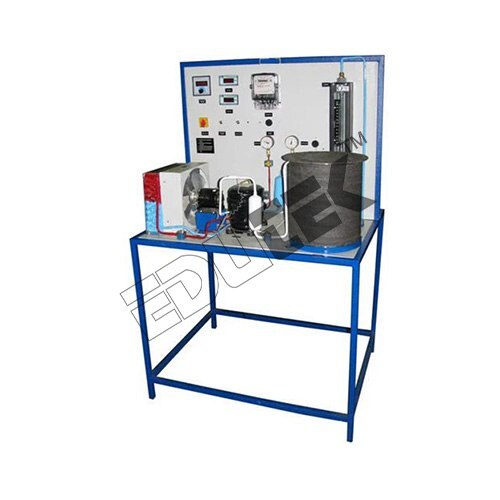 (ET-871U)
VAPOUR ABSORPTION CYCLE TRAINER
Price: 500 INR/Piece
Specification: VAPOUR ABSORPTION CYCLE TRAINER The Vapor Absorption Refrigeration Trainer is designed to demonstrate the working of Aqua-Ammonia Vapor Absorption Refrigeration Cycle & evaluate its performance. The trainer uses packaged refrigerator having electrically heated Generator, Absorber, Condenser, Evaporator mounted in an insulated cabinet where refrigeration load can be applied. The refrigerator uses the mixture of Water & Ammonia as the refrigerant. Due to an absence of mechanical compressor, the refrigerator is quite in operation. Instruments to measure Temperatures at different points, Power Consumption, Heater Load are fitted on Instrument panel. EXPERIMENTAL CAPABILITIES: To identify components of Vapor Absorption Refrigeration System. To plot the vapor absorption cycle on P-h Chart. To calculate COP of Vapor Absorption Refrigeration Cycle. Product Specification Energy meter: Digital Indicator Temperature Sensors: PT 100 temperature sensors -6 Nos Temperature Indicator: 6 Channel Indicator with Selector Switch Frame: Made of M.S. Square Tubes & Sheets, Welded & Powder coated
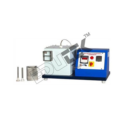 (ET-278L)
TIME CONSTANT OF THERMOCOUPLE & THERMOMETER APPARATUS
Price: 500 INR/Piece
Specification: TIME CONSTANT OF THERMOCOUPLE & THERMOMETER APPARATUS Description: The setup consists of a Heat source controlled with the help of digital temperature controller at any preset value. A thermometer/thermocouple pocket is provided to insert the thermometer/thermocouple in it. The time constant of different thermometer/thermocouple can be calculated with the set-up. A stopwatch is also provided for measurement of time. A Heat sink is fitted to cool down the thermometer/thermocouple. All components are assembled on a base plate to form table top set-up. Experimentation: To determine time constant of a given thermometer/thermocouple Product Details: Usage: Laboratory Voltage: 220 Volt (v) Material: Metal Equipment Materials: Constant of Thermocouple Temperature Range: 40 Celsius (DEGREE C) Display Type: Digital
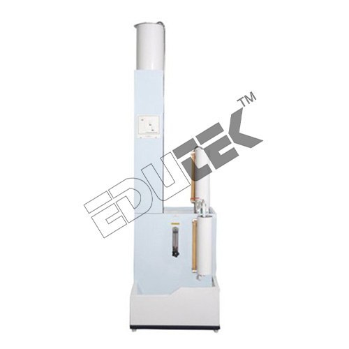 (ET-174N)
TWO TANK INTERACTING SYSTEM APPARATUS
Price: 500 INR/Piece
Specification: TWO TANK INTERACTING SYSTEM APPARATUS Description: The setup studies behavior of multi capacity process when connected in non-interaction mode. It consists of supply tank, pump for water circulation, Rotameter for flow measurement, two independent process tanks with scales connected in non-interacting mode. The components are assembled on frame to form tabletop set-up. Experimentation: To obtain experimentally the step response and to compare the experimental and theoretical responses Product Specifications Usage: Laboratory Material: Metal Equipment Materials: PU Type: Non-Interacting Temperature Range: 35 Celsius (DEGREE C)
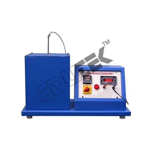 (ET-654C)
MEASUREMENT OF LEVEL BY CAPACITANCE METHOD APPARATUS
Price: 500 INR/Piece
Specification: MEASUREMENT OF LEVEL BY CAPACITANCE METHOD APPARATUS The present set-up is designed to study the working principle and calibration procedure of capacitance type level transmitter. The set-up consists of a probe which is mounted in a level tank with graduated scale. Water is poured in the level tank manually and response of the level transmitter is indicated on the Level Indicator. Output of the transmitter can be measured using Digital Current meter. A drain valve is provided at the bottom of the level tank which enables the student to observe and measure the response of capacitance type level transmitter at different liquid heights. The set-up is complete with Level tank, level transmitter, current indicator and necessary piping. All component and accessories are properly mounted on the rigid MS structure and fitted on a base plate to form a table top set-up. Experimentation/learning objectives: To study of working principle and calibration procedure of capacitance type level transmitter. To study of linearity, accuracy and repeatability of capacitance type level transmitter. Utilities required: Electric supply: Single Phase, 220 V AC, 5-15 amp combined socket with earth connection. Earth voltage should be less than 5 volts. Water supply: Initial fill Floor Drain. Floor area: 1.0 m x 0.5 m Technical details: Level Transmitter: Capacitance type, Input 0-300 mm of water. Output 4-20 mA DC Digital Current Meter: Digital Indication of Current output. Range 0-30 mA DC Level Tank: Acrylic/Glass, PVC Piping: Size ¼ inch
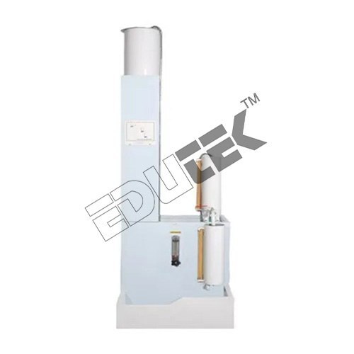 (ET-644O)
SINGLE TANK SYSTEM APPARATUS
Price: 500 INR/Piece
Specification: SINGLE TANK SYSTEM APPARATUS Description The setup is for study of behavior of single tank system. It consists of supply tank, pump for water circulation, Rotameter for flow measurement, and one process tanks with scale. The components are assembled on frame & base plate. Experimentation/Learning Objectives: To obtain the step response of a single tank liquid level system to a step change in input flow and compare it with the theoretical response. To calculate valve resistance. To determine the time constant of the system from the step response curve and compare it with the theoretical value Utilities Required Electric supply: Single Phase, 220 V AC, 5-15 amp combined socket with earth connection. Earth voltage should be less than 5 volts. Water supply Floor Drain Floor area: 1.0 m x 1.0 m
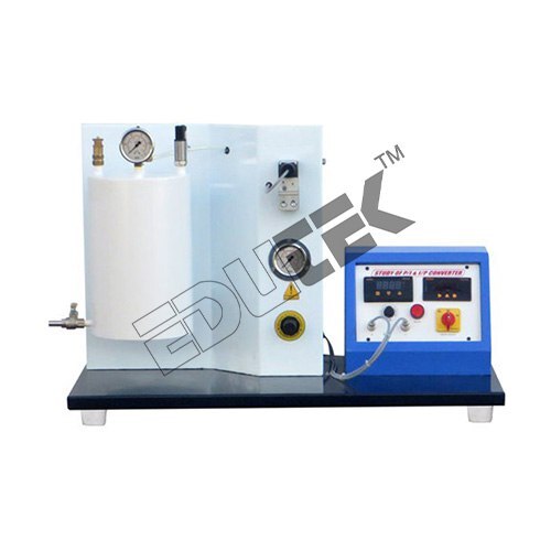 (ET-512F)
STUDY OF P-I & I-P CONVERTOR APPARATUS
Price: 500 INR/Piece
Specification: STUDY OF P-I & I-P CONVERTOR APPARATUS Description: The present set-up is designed to study the working principle and calibration procedure of P/I converter and I/P converter. Air pressure is given to both by compressed air output generated by the both converters is observed and measured. P/I converter accepts the pressure input 0-1 bar and gives output 4-20 mA DC accordingly, which can be measured using Digital Current Source/Meter. And in case of I/P converter, the current input of 4-20 mA DC is given to I/P Converter by Digital Current Source/Meter and output response in 3-15 PSIG is observed and measured by Bourdon type Pressure Gauge. The set-up is self-contained with Air pressure regulator, pressure gauges and necessary piping. All component and accessories are properly mounted on the rigid MS structure and fitted on a base plate to form a table top set-up. Experimentation: To study of working principle and calibration procedure of I/P converter. To study of working principle and calibration procedure of P/I converter. To study of linearity, hysteresis, accuracy and repeatability of I/P and P/I Converter. Product Details: Usage: Laboratory Equipment Materials: SS Type: Convertor Capacity: 500-1000 Kg/hr Temperature Range: 80 Celsius (DEGREE C)
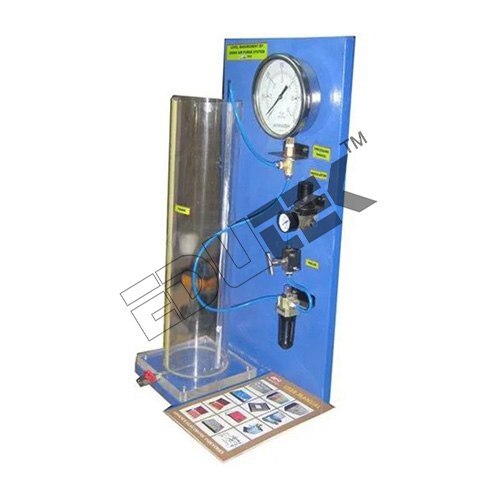 (ET-825P)
MEASUREMENT OF LEVEL BY AIR PURGE METHOD APPARATUS
Price: 500 INR/Piece
Specification: MEASUREMENT OF LEVEL BY AIR PURGE METHOD APPARATUS Salient Features: The EDUTEK Level Measurement by using Air Purge systems is a versatile and standalone system useful for demonstrating the indirect measurement method of measuring level of water in mmwc. The unit consists of a transparent cylindrical tank, calibrated pressure gauge in mmwc, air regulating valve, etc. all mounted on a powder coated platform. Air supply should be provided by the user. Comprehensive instruction manual complete with theory and operating details is provided along with the unit. Technical Specifications Level Tank: Transparent, () 150mm x (H) 600mm Pneumatic Tubing: 1/4. PU Level Indicator: Pressure gauge calibrated in mmwc. Air Regulator: 1/4 air regulating valve, leak proof. Experiments: Study of Level measurement using back pressure. Demonstrate the implicative use of pressure gauge as level measurement (indirect measurement technique).
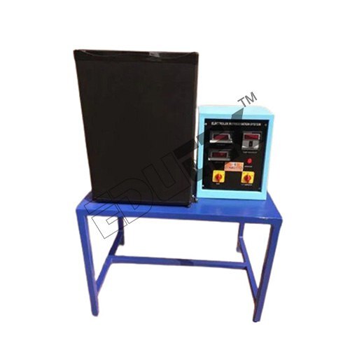 (ET-211N)
ELECTROLUX REFRIGERATION TEST RIG
Price: 500 INR/Piece
Specification: ELECTROLUX REFRIGERATION TEST RIG Description: The set up demonstrates the students about the basic principal of a vapor absorption refrigeration cycle. The test rig is designed for the study of thermodynamics of vapor absorption refrigeration cycle by measuring temperature at different position. Experimentation: To Calculate Co-efficient of performance. Utilities Required: Electric Supply: Single Phase, 220 V AC, 50 Hz, 5-15 Amp. Combined socket with earth connection. Bench Area: 1.5 m x 1m Technical Details: Sealed Circuit: The System has no moving parts at all, which makes it Silent and very durable. Refrigerant: Mixture of three fluid system Ammonia (NH3) Water (H2O) hydrogen (H2) Gases: Non“CEC, Non “HCFC, Non“FCKW, Non “Freon Mode of System: Externally heated by electric resistance Evaporator: Coil Type evaporator with facility to determine performance efficiency ratio (PER) Volume of Cabinet: 41 Ltrs., Voltage Input “65 Watts, Electrical Consumption/24 Hrs. “0.8 kWh, Auto Defrost Fuzzy Logic System, Voltage Temperature Measurement: Digital Temperature Indicator with multi-channel switch. Temperature Sensor: RTD PT-100 Type. Digital Voltmeter: 0-300 V Digital Ammeter: 0-5 Amp.
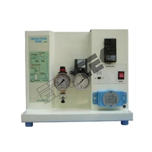 (EDPC-9104)
PRESSURE CONTROL TRAINER (COMPUTER CONTROLLED SYSTEM) APPARATUS
Price: 500 INR/Piece
Specification: PRESSURE CONTROL TRAINER (COMPUTER CONTROLLED SYSTEM) APPARATUS Pressure control trainer is designed for understanding the basic principles of pressure control. The process set up consists of pressure vessel fitted with pneumatic control valve. Pressure transmitter is used for pressure sensing. The process parameter (Pressure) is controlled by microprocessor based digital indicating controller which manipulates pneumatic control valve fitted at outlet of pressure tank outlet through I/P converter. These units along with necessary piping are fitted on support housing designed for tabletop mounting. The controller can be connected to computer through USB port for monitoring the process in SCADA mode. Product is supplied with 32-point demo version of SCADA software package.
 (ET-757R)
FIXED & FLUIDIZED BED APPARATUS
Price: 500 INR/Piece
Specification: FIXED & FLUIDIZED BED APPARATUS Voltage: 500 watts, 220V, 1 Phase. Usage/Application: Industrial Capacity: 30 LTR Power: 500 watts, 220V, 1 Phase. Body Material: Stainless Steel Country of Origin: Made in India
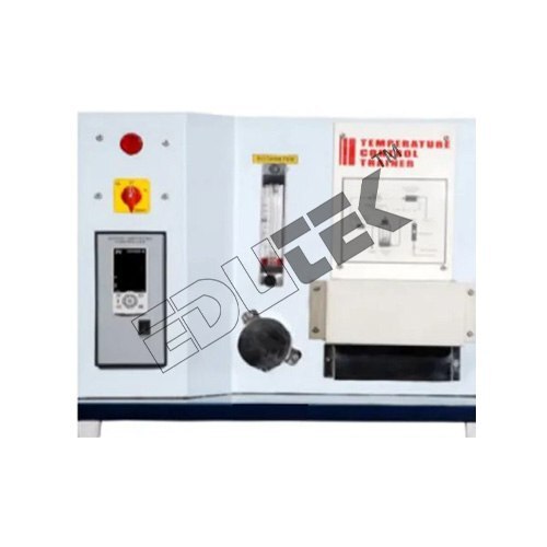 (ET-385G)
TEMPERATURE CONTROL TRAINER (COMPUTER CONTROLLED SYSTEM) APPARATUS
Price: 500 INR/Piece
Specification: TEMPERATURE CONTROL TRAINER (COMPUTER CONTROLLED SYSTEM) APPARATUS The process setup consists of heating tank fitted with thyristor-controlled heater for on line heating of the water. Water is supplied from laboratory constant head tank and its flow can be manipulated and measured by provided Rotameter. The temperature of the heated water is sensed by RTD sensor. This measured variable through Temperature Transmitter is communicated to Digital Indicating Controller. Error is calculated and output, accordingly, is communicated to Thyristor Controlled heater to achieve the Set Point. These units along with necessary piping are supported in a well-designed housing and are fixed on base plate. Experimentation: To study the open loop or manual control To study the proportional control To study the two mode (P+I) control To study the two mode (P+D) control To study the three mode (PID) control To study the tuning of controller (Open loop method) using Zeigler-Nichols method. To study the stability of the system using the BODE PLOT. Auto Tuning Technical Detail: Temperature Transmitter: Input RTD PT-100 (0-100C), output 4-20 mA. Process tank: Material Stainless Steel, Heater: Nichrome Wire Heater, Capacity 1 Kw Thyristor Controller: Input 4-20mA for heater. Flow Measurement: Rotameter. Piping: Size 1/4 Interfacing unit: For input-output communication with auto/manual facility Micro-processor Controller: PID Setting, auto tuning, fully programmable with serial communication. Software: For experimentation, PID control, Data logging, trend plot, offline analysis and printing.
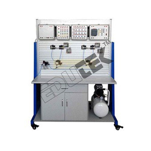 (ET-616T)
ELECTRO PNEUMATIC TRAINER
Price: 500 INR/Piece
Specification: ELECTRO PNEUMATIC TRAINER The components are capable of being mounted on an appropriate profile plate with grooves for secure and flexible positioning so that the components can be clamped firmly, quickly and safely through quick fix adaptors. Industrial components are used in the kit so that the students get hands on practical training in using industrial components. Advanced customized electro-pneumatic trainer kit is capable of being used to demonstrate the design, construction and application of electro-pneumatic components and circuits. The Kit is designed to satisfy following objectives: Direct and indirect manual controls, stroke dependent controls, time dependent and pressure dependent controls with time delay, pressure sequence valves. Design & function of an electro-pneumatic System. Function & identification of Electro-pneumatic components & their symbols. Functional diagrams. Logic AND/OR function to start signals. To empower students to design their own circuits. The kit is modular and upgradeable.
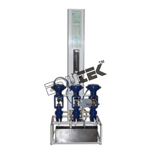 (EDPC-9105)
CONTROL VALVE CHARACTERISTICS APPARATUS
Price: 500 INR/Piece
Specification: CONTROL VALVE CHARACTERISTICS APPARATUS The setup is designed to understand the control valve operation and its flow characteristics. It consists of pneumatic control valves of linear, equal% (& quick opening for product 318B) type, stainless steel water tank with pump for continuous water circulation and rotameter for flow measurement. An arrangement is made to measure pressure at the valve inlet in terms of mm of water. An air regulator and pressure gauge are provided for the control valve actuation. In case of additional optional requirement, a valve positioner is fitted on linear valve. The setup is stand-alone type.
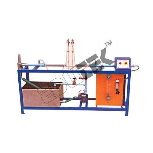 (ET-11987C)
PRESSURE DROP IN TWO PHASE FLOW APPARATUS
Price: 500 INR/Piece
Specification: PRESSURE DROP-IN TWO-PHASE FLOW APPARATUS Edutek are manufacturers, exporters and suppliers of Pressure Drop-in Two-Phase Flow that is manufactured from high-grade raw materials. Keeping an eye on current market trends, our diligent workers put in sincere efforts to manufacture the offered range. The provided product is uniquely designed in compliance with international quality standards, using optimum quality raw materials and latest technology. Further, our valuable clients can avail this range in diverse specifications in compliance with details specified by clients. Features: Anti-corrosive High strength Fine finish Test Section Material Borosilicate Glass Water Circulation FHP Pump, Crompton/Sharp make Flow Measurement Rotameters. 2 Nos. (one each for Water & Air). Air Circulation by Compressed Air Buffer Tank Material Stainless steel, Suitable Capacity with Safety valve and Pressure Gauge Water Tank Material Stainless Steel/PVC, Capacity 60 Ltrs Pr. Drop measurement Differential Manometer Separator Material Stainless steel, Compatible capacity Piping GI and PVC Control panel comprising of Standard make on off switch, Mains Indicator fuse etc. The whole set-up is well designed and arranged in a good quality painted structure.
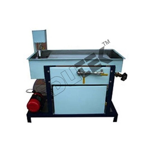 (ET-308HP)
HYDRODYNAMICS OF PACKED BED APPARATUS
Price: 500 INR/Piece
Specification: HYDRODYNAMICS OF PACKED BED APPARATUS Material: Stainless Steel Application: For Laboratory Weight: 10-50 Kilograms (kg) Product Type: Hydrodynamics of Packed Bed Voltage: 110-220 Volt (v)
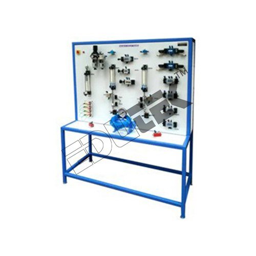 (ET-878M)
DEMONSTRATION WORKING MODEL OF PNEUMATIC CIRCUIT OF SPEED CONTROL OF DOUBLE ACTING CYLINDER
Price: 500 INR/Piece
Specification: DEMONSTRATION WORKING MODEL OF PNEUMATIC CIRCUIT OF SPEED CONTROL OF DOUBLE ACTING CYLINDER Pneumatic Circuit for Speed Control of Double Acting Cylinders. Pneumatic cylinders can be directly controlled by actuation of final directional control valve as shown in fig. These valves can be controlled manually or electrically. This circuit can be used for small cylinders as well as cylinders which operates at low speeds where the flow rate requirements are less. When the directional control valve is actuated by push button, the valve switches over to the open position, communicating working source to the cylinder volume. This results in the forward motion of the piston. When the push button is released, the reset spring of the valve restores the valve to the initial position [closed]. The cylinder space is connected to exhaust port there by piston retracts either due to spring or supply pressure applied from the other port.
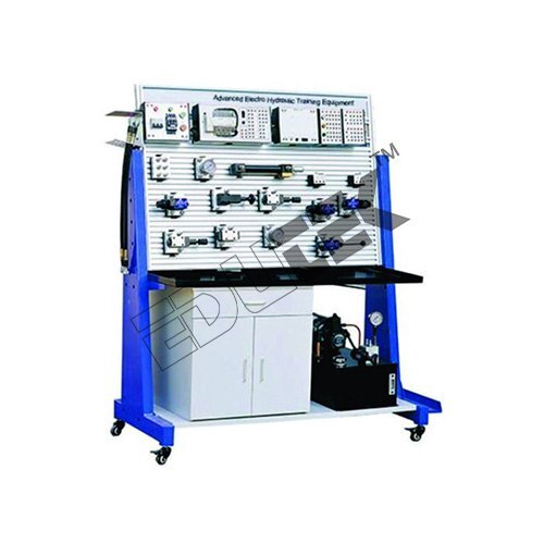 (ET-83326A)
ELECTRO HYDRAULIC TRAINER
Price: 500 INR/Piece
Specification: ELECTRO HYDRAULIC TRAINER Material: Mild Steel Surface Finishing: Polished Voltage: 220V Frequency: 50 Hz-60 Hz Power Source: Electric Power: 2.5 KW
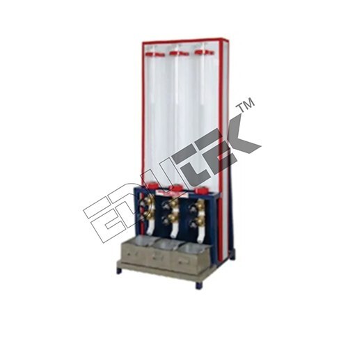 (ETDC-64)
DRAG COEFFICIENT APPARATUS
Price: 500 INR/Piece
Specification: DRAG COEFFICIENT APPARATUS In order to meet the varied demands of the clients, we have come up with Drag Co-Efficient Apparatus. These are designed to determine the relationship between the drag coefficient of falling particles and their Reynolds number value. To conduct detailed experiments the product is provided with several vertical glass tube with two marks on the walls that allows single particles to fall from them and enables easy observation. Further the product is provided with a value system at the bottom for easy removal of the particles with minimum loss of liquid. Scope Of Experimentations: To study the motion of a solid particle through a liquid. To plot the graph between drag coefficient VS. modified Reynolds number. To measure the drag Coefficient. Utilities Required. Liquids of different viscosity. Electricity supply 100 watts, 220 V, 1 phase. Floor Area 0.75 m x 1.5 m. Technical Details. Provided with steel and glass balls of different sizes. The whole set-up is well designed and arranged in a good quality painted structure having the tube light arrangement. Stop Watch. Electronic. Material Borosilicate Glass tube. Gate Valves. 6 Nos. (2 Nos. on each Tube). Tubes (3 Nos.).
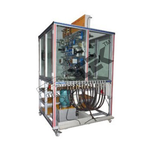 (ET-579S)
HYDRAULIC TRAINER (PLC CONTROL)
Price: 500 INR/Piece
Specification: HYDRAULIC TRAINER (PLC CONTROL) Electro-hydraulics with PLC controls is widely used in all industries for a variety of applications. The combination of PLC, electrical controls and hydraulics is very effective in automation and Mechatronics.
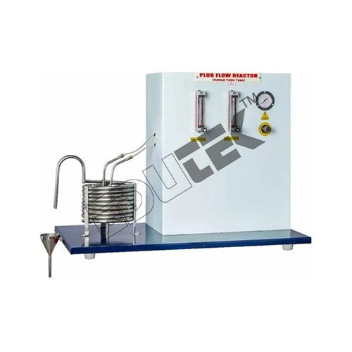 (ET-769M)
PLUG FLOW TUBULAR REACTOR (COILED TUBE TYPE) APPARATUS
Price: 500 INR/Piece
Specification: PLUG FLOW TUBULAR REACTOR (COILED TUBE TYPE) APPARATUS In an ideal Plug Flow Reactor (PFTR) there is no mixing in the direction of flow and complete mixing perpendicular to direction of flow. Concentration of reactants varies along the length of reactor but not in radial direction. This set-up is used to study a non-catalytic homogeneous reaction under ambient condition. The set up consists of two feed tanks through which two reactants are fed to the reactor. It is a helical coil tube type reactor. Rotameters are provided to measure the individual flow of Chemicals. The flow rate can be adjusted by operating the needle valves provided on respective Rotameter. The compressed air is used for circulation of feed. Samples are collected for analysis from the outlet of reactor. Pressure Regulator, Pressure Gauge and Safety Valve are fitted in the compressed airline. Product Specification Reactor: Material Stainless Steel, Volume (0.6-0.7) Ltrs (approx.). Feed Tank: Material Stainless Steel, Capacity - 20 Ltrs. (approx.) Feed Circulation: By compressed air. Flow Measurement: Rotameter 2 Nos. (One each for Reactants). Piping: Stainless Steel and PU pipe Pressure Regulator: 0-2 Kg/cm2.
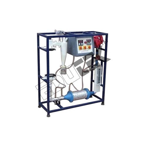 (ET-193A)
FLUIDIZED BED CHARACTERISTICS APPARATUS
Price: 500 INR/Piece
Specification: FLUIDIZED BED CHARACTERISTICS APPARATUS Edutek We are leading manufacturer and exporter of a wide range of Fluidized Bed Dryer. The Salt is fluidized, each particle meets the hot air, discharges moisture, gets dry and at the same time travels forward without any mechanical push. We have proven-technology for designing dryers of any capacity. In this state, the solids behave like a free-flowing boiling liquid. Clients can avail this product as per there requirements. Scope of Experimentations: To study fluidization characteristics To study relationship between velocity of fluid and pressure drop per unit length Utilities Required: Electricity: 500 watts, 220 V, 1 Phase Floor Area: 0.75 m x 0.75 m Technical Details: Column: Material Borosilicate Glass Packing: Glass Beads Water tank: Material Stainless Steel, Capacity 30 Ltrs Water Circulation: FHP Pump, Crompton/Sharp make Flow Measurement: Rotameter for water Pr. Drop Measurement: Manometer The whole set-up is well designed and arranged in a good quality painted structure
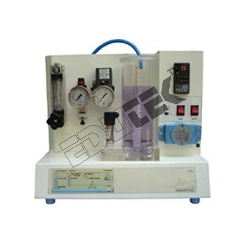 (ET-543B)
LEVEL CONTROL TRAINER (COMPUTER CONTROLLED SYSTEM) APPARATUS
Price: 500 INR/Piece
Specification: LEVEL CONTROL TRAINER (COMPUTER CONTROLLED SYSTEM) APPARATUS Level control trainer is designed for understanding the basic principles of level control. The process setup consists of supply water tank fitted with pump for water circulation. The level transmitter used for level sensing is fitted on transparent process tank. The process parameter (level) is controlled by microprocessor based digital indicating controller which manipulates pneumatic control valve through I/P converter. A pneumatic control valve adjusts the water flow in to the tank. These units along with necessary piping are fitted on support housing designed for tabletop mounting. Feature The controller can be connected to computer through USB port for monitoring the process in SCADA mode. Product is supplied with 32-point demo version of SCADA software package
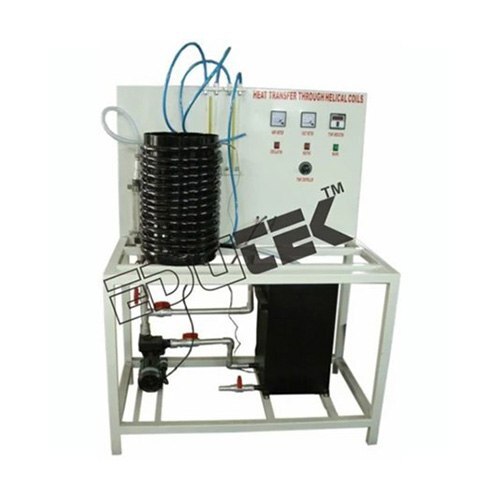 (ET-11987B)
FLOW THROUGH HELICAL COIL APPARATUS
Price: 500 INR/Piece
Specification: FLOW THROUGH HELICAL COIL APPARATUS Delivering a wide gamut of Flow Through Helical Coil. This coil is designed by our adroit professionals using high-grade raw materials and modish technology, who have in-depth knowledge about the industrial standards. Available with us in numerous specifications, to meet the varied demands of our respectable clients. Features: Rust proof, Less maintenance, Maximum strength Specifications: Helical Coil Material Stainless Steel Dia “ 12, No. of Turns 15, Coil Tube Dia OD 21mm, ID 17mm (Approx.), Sump Tank Material Stainless Steel/PVC, Capacity 50 Ltrs, Water Circulation FHP Pump, Crompton/Sharp, Manometer 2 Nos., Flow measurement Rotameter, Piping GI and PVC, Control panel comprising of Standard make on off switch, Mains Indicator etc. The whole set-up is well designed and arranged in a good quality painted structure
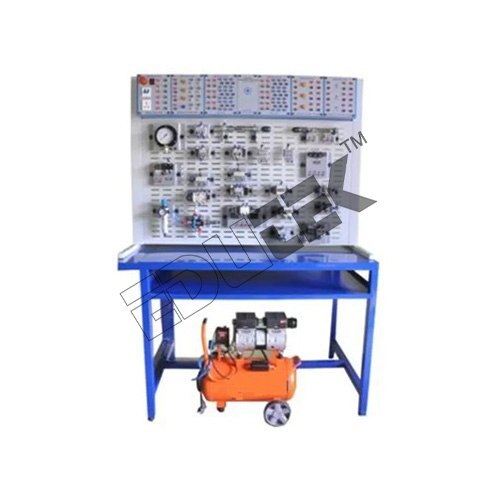 (ET-246K)
DEMONSTRATION WORKING MODEL OF PNEUMATIC CIRCUIT OF SPEED CONTROL OF PNEUMATIC MOTOR
Price: 500 INR/Piece
Specification: DEMONSTRATION WORKING MODEL OF PNEUMATIC CIRCUIT OF SPEED CONTROL OF PNEUMATIC MOTOR The speed control of motor by using variable two flow control valves having built-in check valve and 4x3 DC valve having zero position or central hold position with lever L1 and L2. When lever L1 is operated, port P will be connected to port A of air motor and motor will start rotating in clockwise direction.
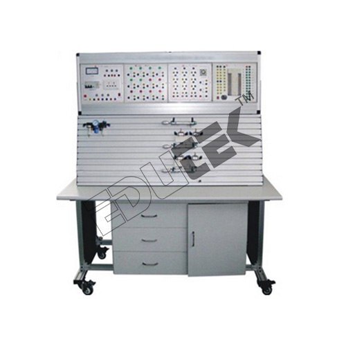 (ETK-1169)
PNEUMATIC TRAINER
Price: 500 INR/Piece
Specification: PNEUMATIC TRAINER This trainer Very useful to study the Basic Level Pneumatics Kit Components like FRL, Pilot valve, cylinder etc. Students can make Design and verifies the circuit pneumatic level operation using this kit.
 (ET-230N)
R.T.D. STUDIES IN PLUG FLOW TUBULAR REACTOR (STRAIGHT TUBE TYPE) APPARATUS
Price: 500 INR/Piece
R.T.D. STUDIES IN PLUG FLOW TUBULAR REACTOR (STRAIGHT TUBE TYPE) APPARATUS DESCRIPTION: Real reactors do not satisfy the idealized flow patterns, back mix flow or plug flow deviation from ideality can be due to channeling of fluid through the vessel, recycling of fluid within the vessel or due to the presence of stagnant region or pockets of fluid in the vessel. To predict the exact behavior of a vessel as a Chemicals reactor, RTD or stimulus response technique is used. The set up consists of one overhead feed tank through which water is fed to the reactor. Rotameter is provided to measure flow of water. The flow rate can be adjusted by operating the needle valve provided on rotameter. A straight tube type reactor kept horizontally and inclined upward at outlet from where samples are collected for analysis. For understanding the R.T.D. characteristics, a special arrangement to inject tracer into the lower end of reactor, using a syringe is provided. EXPERIMENATION: To plot RTD curve for Plug Flow Reactor. To determine the Dispersion No. Product Specifications Material: Metal Usage: Laboratory Machine Operate Method: Manual Equipment Materials: SS
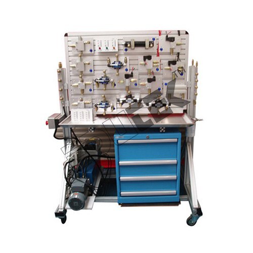 (ETK-1166)
HYDRAULIC TRAINER
Price: 500 INR/Piece
Specification: HYDRAULIC TRAINER Hydraulic is a self “ contained where demonstration of over 15 experiments is possible. Hydraulic Trainer is a sophisticated, indigenous, new generation hydraulic teaching aid, specially developed to impart the best practical training in basic hydraulics. It can be used as a Live Demonstrator to show functioning of various hydraulic components and control circuits. Operating pressure is kept at 20 bar for safety of the students. The components / equipment™s are mounted on an ergonomically designed mobile metal trolley with drip tray. The power pack is mounted at the bottom. The components are permanently mounted on the working area. "Quick Release Couplings are used on the components and hoses for fast and easy connections
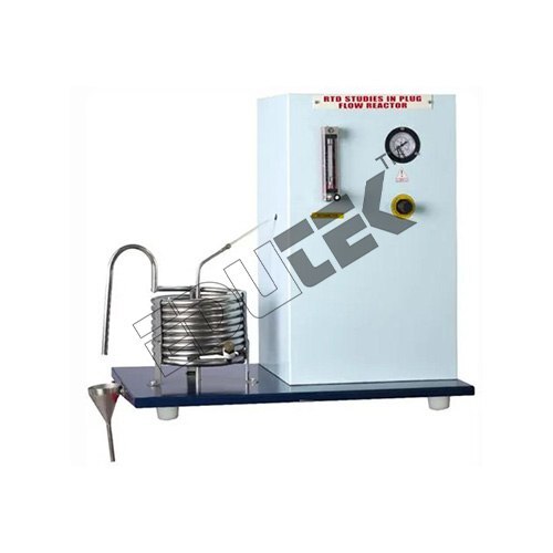 (ET-508U)
R.T.D. STUDIES IN PLUG FLOW TUBULAR REACTOR (COILED TUBE TYPE) APPARATUS
Price: 500 INR/Piece
Specification: R.T.D. STUDIES IN PLUG FLOW TUBULAR REACTOR (COILED TUBE TYPE) APPARATUS Description: Real reactors do not satisfy the idealized flow patterns, back mix flow or plug flow deviation from ideality can be due to channeling of fluid through the vessel, recycling of fluid within the vessel or due to the presence of stagnant region or pockets of fluid in the vessel. To predict the exact behavior of a vessel as a Chemicals reactor, RTD or stimulus response technique is used. The setup consists of one feed tank through which water is fed to the reactor. The flow rate can be adjusted by operating the needle valve and measured by Rotameter. The compressed air is used for circulation of feed. It is a helical coil tube type plug flow reactor made up of Stainless-steel pipe. Reactants enter at lower end coming out of the top of coil from where samples are collected for analysis. For understanding the R.T.D. characteristics, a special arrangement to inject tracer into the lower end of reactor, using a syringe is provided. Pressure Regulator & Pressure Gauge are fitted in the compressed air line. Experimentation: To plot RTD curve for Plug Flow Reactor. To determine the Dispersion No. Product Specifications Material: Metal Voltage: 240 Volt (v) Usage: Laboratory Equipment Power: 500 Watt (w) Equipment Materials: SS
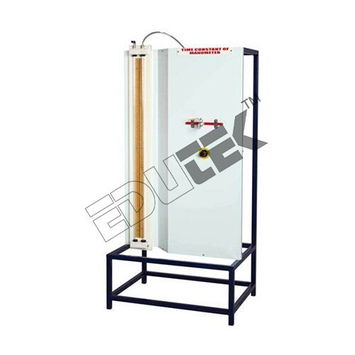 (ET-994N)
TIME CONSTANT OF MANOMETER APPARATUS
Price: 500 INR/Piece
Specification: TIME CONSTANT OF MANOMETER APPARATUS Description: The present set-up is designed to study the characteristics of a U Tube manometer. It consists of a U Tube manometer, which is pressurized by air. A suitable and proper arrangement has done for charging and discharging the manometer fluid in the manometer. This arrangement facilitates to observe the response of different types of manometer fluids of different heights. An air pressure regulator is provided to change the pressure in the manometer. All components are assembled on a frame to form a tabletop set-up. Experimentation: To find the characteristics of U tube manometer. To estimate the theoretical time constant and damping coefficient of the manometer. To plot the graphs with damping co-efficient as abcirra and decay ratio, overshoot and frequency of oscillation as ordinates. Product Details: Material: Metal Usage: Laboratory Type: Constant of Manometer Temperature Range: 60 Celsius (DEGREE C)
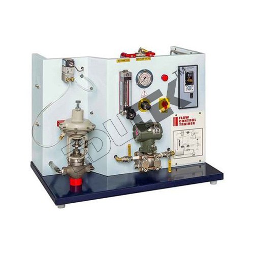 (ET-267V)
FLOW CONTROL TRAINER (COMPUTER CONTROLLED SYSTEM) APPARATUS
Price: 500 INR/Piece
Specification: FLOW CONTROL TRAINER (COMPUTER CONTROLLED SYSTEM) APPARATUS Description: The present set-up is designed to study a PID Controlled Flow Process in the industry. Water is pumped from the sump tank by means of a centrifugal pump to a Pneumatic Control Valve and after passing thorough the Rotameter it return back to the sump. The Differential Pressure transmitter with an Orifice meter is fitted in the water line. The flow of water in the line is sensed by the transmitter and communicated to the digital indicating controller. This measured variable is compared with the Set Point by controller and output is generated and given to I/P converter, which in turn supply the 3-15 Psig pressure to vary the opening of the Pneumatic control valve to eliminate the error observed. As the opening of pneumatic control valve varies, the flow of water in the line gets effected. This process goes on until the Set Point target is achieved. A ball valve is also provided in the water line to disturb the system and to observe the effect of disturbance. As the water returns in the sump tank again, the system operates in close circuit. Provided Rotameter enables to get the direct reading of flow of water in the line. These units along with necessary piping are supported in a well-designed housing and are fixed on base plate. Experimentation: To study the open loop or manual control To study the proportional control To study the two mode (P+I) control To study the two mode (P+D) control To study the three mode (PID) control To study the tuning of controller (Open loop method) using Zeigler-Nichols method. To study the stability of the system using the BODE PLOT. Auto Tuning Product Specifications Material: Metal Usage: Laboratory Voltage: 220 Volt (v) Equipment Materials: Brass Type: Flow Control Temperature Range: 60 Celsius (DEGREE C)
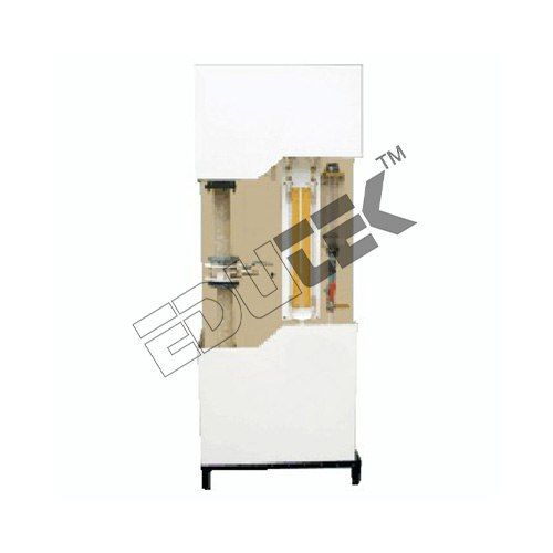 (ETPT-66)
PRESSURE DROP THROUGH PACKED BED APPARATUS
Price: 500 INR/Piece
Specification: PRESSURE DROP THROUGH PACKED BED APPARATUS Edutek Pressure Drop Through Packed Bed. Under the supervision of our skilled technocrats, these machines are manufactured as per the latest technological advancements utilizing quality approved raw materials. Offered product is acknowledged for its robust construction, low maintenance, longer functional life and energy efficiency. We offer pressure drop in both, standard and customized specifications to our valuable clients. Features: Highly efficient Premium quality Durable finish Specifications: Packed Column Material Borosilicate Glass with both end made of Stainless Steel Packing Material Borosilicate Glass rings, Size 8-10mm approx. Water tank Material Stainless Steel, Capacity 30 Ltrs Water Circulation FHP Pump Crompton/Sharp make Flow Measurement Rotameters for water Drop Measurement Manometer The whole set-up is well designed and arranged in a good quality painted structure
 (ET-276C)
PNEUMATIC TRAINER (PLC CONTROL)
Price: 500 INR/Piece
Specification: PNEUMATIC TRAINER (PLC CONTROL) Phase: Single Phase Voltage (V): 220 V Power Source: Electricity Frequency (Hz): 50 Motor (Hp): 1- 3 Table Frame Material: Stainless Steel
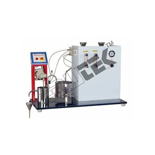 (ET-338N)
COMBINED FLOW REACTOR APPARATUS
Price: 500 INR/Piece
COMBINED FLOW REACTOR APPARATUS This set-up is used to study a non-catalytic homogeneous second order liquid phase reaction under ambient condition in a combined reactor. It consists of two reactors connected in series; one is plug flow reactor and another is CSTR. In an ideal Plug Flow Reactor (PFTR) there is no mixing in the direction of flow and complete mixing perpendicular to direction of flow. Concentration of reactants varies along the length of reactor but not in radial direction. In case of a coil turbulence is introduced due to frequent change in direction of flow and presence of secondary flow, so a higher value of reaction rate constant is expected in coil tube type plug flow reactor. In an ideal CSTR the contents in reactor are well mixed and have uniform composition throughout. Thus the exit stream has the same composition as the fluid within the reactor. The set up consists of two feed tanks through which two reactants are fed to the reactors fitted in series. Rotameters are provided to measure the individual flow of Chemicals. The flow rate can be adjusted by operating the needle valves provided on respective rotameter. The compressed air is used for circulation of feed. 1st is a helical coil tube type reactor made up of SS pipe. Reactants enter at lower end coming out of the top of coil from where it is fed to CSTR fitted with stirrer for proper mixing. Samples are collected for analysis. Pressure Regulator, Pressure Gauge and Safety Valve are fitted in the compressed air line. Product Specification Reactor 1: Helical Coil Tube Type, Capacity 1 Liter approx. made of stainless steel 304 grade. Reactor 2: CSTR made of stainless steel 304 grade, Material Stainless Steel 304 grade, Capacity 1 Liter (approx.) Stirrer for CSTR: Stainless Steel Impeller and shaft coupled with FHP motor Feed Tank: Material Stainless Steel, Capacity 20 Ltrs. Feed circulation: By compressed air Flow Measurement: Rotameter 2 Nos. (One each for Reactants).
 (ET-489O)
SPIN INNING BASKET REACTOR APPARATUS
Price: 500 INR/Piece
Specification: SPIN INNING BASKET REACTOR APPARATUS Description Any catalytic liquid-liquid or liquid-gas reaction involving the use of a catalyst placed in basket can be studies in this set-up. Kinetic parameter of a specific reaction can be estimated & parametric studies can be conducted. The set-up consists of a reactor centrally having one spinning basket derived through a variable speed motor. The metered flow of reactant from feed tank is fed to the reactor at the bottom. The set-up can be used as batch wise of as continuous type. Sampling points are provided for analysis. Port connection for gas inlet is provided at the bottom of the reactor Experimentation/Learning Objectives To determine the kinetic parameters for a given reaction Utilities Required Electricity Supply: Single Phase, 220 V AC, 50 Hz, 5-15 Amp combined socket with earth connection. Earth voltage should be less than 5 volts. Compressed air supply@1 Bar. Water Supply. Floor Drain. Floor Area Required: 1.0 m x 0.75 m. Instruments, Laboratory Glassware and Chemicals required for analysis as per the system adopted Technical Details Reactor Vessel: Material Stainless Steel Effective Volume: 1000 ml. Basket: Material Stainless Steel, Fitted with appropriate Stainless Steel. Drive for Basket: DC Motor with Thyristor controlled DC Drive for Variable Speed. Packing: Catalyst Feed Tank (1Nos.): Material Stainless Steel, Capacity 10 Ltrs. Flow Measurement: By Rotameter Pressure regulator: Range 0-2 kg/cm² Pressure Gauge: Bourdon Type, 0-2 kg/cm² Receiver: Material Stainless Steel, Capacity 10 Ltrs. Piping: Stainless Steel and PVC. Hot water Circulation: Magnetic Pump of Poly propylene (in outer Jacket) to circulate Hot Water maximum working temp. 85C Hot water tank: Made of Stainless Steel, Double wall, insulated with Ceramic Wool. Capacity: 10-15 ltrs.
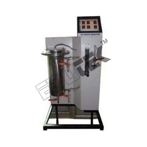 (ET-952B)
UV-PHOTO REACTOR APPARATUS
Price: 500 INR/Piece
Specification: UV-PHOTO REACTOR APPARATUS Description The set-up is used to study a photo catalytic reaction using a UV source provided in the form of an UV tube. This set-up can be used to carry out a parameter study under batch/continuous flow condition. A photo catalyst like TiO2 can be used. This set-up can also be used to study the mineralization of liquid effluent industrial streams & for purification of water. The set-up consists of reactor with inside reflecting surface. An UV source surrounding glass/quartz cylinder is placed centrally in the reactor Utilities Required Electricity Supply: Single Phase, 220 V AC, 50 Hz, 5-15 Amp combined socket with earth connection. Earth voltage should be less than 5 volts. Water Supply Floor Drain. Instruments, Laboratory wares and Chemicals required for analysis as per the system adopted Technical Details UV Source: 30 W / 16 W Reactor: With inside reflective surface. Effective volume of reactor 1-1.5 Ltrs. Feed Tank: Material Stainless Steel, Capacity 5 Ltrs. Feed circulation: Magnetic Pump made of Polypropylene. Maximum working temperature 80C. Flow Measurement: By Rotameter
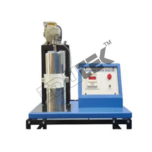 (ET-919C)
ADIABATIC BATCH REACTOR APPARATUS
Price: 500 INR/Piece
Specification: ADIABATIC BATCH REACTOR APPARATUS An adiabatic batch reactor is a closed system with no input and output streams. This reactor is operated under conditions like adiabatic (Temperature of Reaction Mass keep on changing), perfectly mixed (composition of the reaction mixture is uniform throughout), and constant volume (volume of the reaction mixture within the reactor remains constant, there is no appreciable change in the density of reaction mass). This setup is used to study a catalytic homogeneous reaction under adiabatic conditions. The set-up consists of a Dewar flask of a capacity of 1 lit. Fitted with a stirrer. The flask is double insulated by ceramic wool insulation. Temp., is measured by a digital temp indicator. The whole setup is mounted on a rigid M.S. frame. Experimentation/Learning Objectives To study the decomposition of Hydrogen Peroxide with water in presence of an Iodide catalyst. To predict the degree of conversion from time-temperature data Utilities Required Hz, 5-15 Amp combined socket with earth connection. Earth voltage should be less than 5 volts. Floor Area Required: 1.0 m x 1.0 m. Instruments, Laboratory Glassware, and Chemicals required for analysis as per the system adopted. Product Specification Material: Stainless Steel Capacity: 1 litre Country of Origin: Made in India Temp. Indicator: Digital Floor Area Required: 1.0 m x 1.0 m
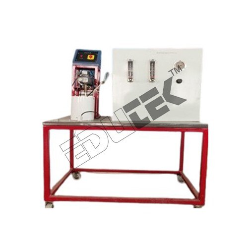 (ET-762H)
RECYCLE BED REACTOR APPARATUS
Price: 500 INR/Piece
Specification: RECYCLE BED REACTOR APPARATUS Description The setup consists of catalyst packed column of Stainless Steel. Reactant from a fed tank is fed to the reactor through liquid distributor, fitted at one end of the column. Some part of product is recycled to the reactor using a low capacity sophisticated pump or by overhead tank system. Rotameters are provided to measure the flow of feed & recycled product. The feed rate and recycle product ratio can be manipulated by the respective needle valves of the rotameter. Samples can be taken periodically from the top outlet of reactor at another end. An arrangement is made to carry out the reaction at Isothermal conditions by circulating the hot water in the outer jacket of the packed bed reactor. Arrangement is done for proper mixing of feed & recycle product before its entry to the reactor. A magnetic drive pump made up of poly propylene is used for circulation of feed. Experimentation/Learning Objectives To determine the Reaction Rate Constant. Utilities Required Electricity Supply: Single Phase, 220 V AC, 50 Hz, 5-15 Amp combined socket with earth connection. Earth voltage should be less than 5 volts. Water Supply. Floor Drain. Floor Area Required: 1.0 m x 0.75 m. Instruments, Laboratory Glassware and Chemicals required for analysis as per the system adopted Technical Details Reactor Column: Material Stainless Steel Diameter 25mm (approx.), Length: 500mm (approx.). Packing: Catalyst Feed Tank (1Nos.): Material Stainless Steel, Capacity - 20 Ltrs. Flow Measurement: Rotameter 2Nos. (One each for feed & recycled product). Piping: Stainless Steel and PVC. Feed Circulation: Magnetic Pump of Poly propylene. Hot water tank: Made of Stainless steel, Double wall, insulated with Ceramic Wool, Capacity: 10-15 ltrs. Hot water Circulation: Magnetic Pump of Poly propylene to (in outer Jacket) circulate Hot Water maximum working temp. 85C
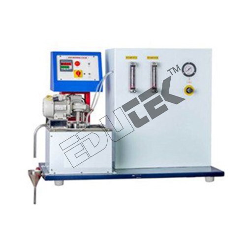 (ET-861J)
ISOTHERMAL CONTINUOUS STIRRED TANK REACTOR (C.S.T.R.) APPARATUS
Price: 500 INR/Piece
Specification: ISOTHERMAL CONTINUOUS STIRRED TANK REACTOR (C.S.T.R.) APPARATUS Description: In an ideal CSTR (i.e. an ideal steady state flow reactor) the contents in reactor are well mixed and have uniform composition throughout. Thus the exit stream has the same composition as the fluid within the reactor. This type of reactor is known as mixed flow reactor. This set-up is used to study a non-catalytic homogeneous second order liquid phase reaction under isothermal condition. The set up consists of two feed tanks through which two reactants are fed to the reactor. The flow rate can be varied by changing the speed of peristaltic pump. The CSTR is fitted with stirrer for proper mixing. From top outlet of it samples are collected for analysis. Constant temperature water bath arrangement is provided to conduct the experiment at various temperatures. Experimentation: Saponification Reaction study in Isothermal CSTR. To determine the Reaction Rate Constant and effect of temperature on it. Product Details: Voltage: 220 Volt (v) Usage: Laboratory Material: Metal Equipment Materials: SS Temperature Range: 30 Celsius (DEGREE C) Display Type: Digital
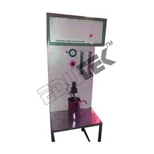 (ET-136O)
LIQUID PHASE CHEMICAL REACTOR APPARATUS
Price: 500 INR/Piece
Specification: LIQUID PHASE CHEMICAL REACTOR APPARATUS Description Present set-up consists of a reactor vessel fitted with variable speed agitator and detachable baffles. This unit is designed to study chemical kinetics. Reactants are fed to the reactor, using pump and flow is regulated and monitored by individual Rotameter. An adjustable overflow device is provided in the reactor to conduct the experiment on different reactor volume. A Stainless-Steel Coil is immersed in the reactor through which the hot water supply is circulated. Temperature of the hot water is controlled by means of Temperature Controller and it enables the students to enhance the experimentation capabilities Experimentation/Learning Objectives To study the chemical kinetics. To study the effect of residence time. To study the effect of mixing speed. To study the effect of temperature on chemical reaction. Utilities Required Electricity Supply: Single Phase, 220 V AC, 50 Hz, 5-15 Amp combined socket with earth connection. Earth voltage should be less than 5 volts. Water Supply Floor Drain. Floor Area Required: 1.5 m x 1 m. Instruments, Laboratory wares and Chemicals required for analysis as per the system adopter Technical Details Reactor: Material SS, Capacity (1-2) Ltrs. Agitator: Variable speed with speed control facility from 0 “ 150 RPM. Impeller: 4 square bladed (1 No.), Material- Stainless Steel. Baffles: Detachable. Piping: PVC. Feed Tank (2Nos.): Material Stainless Steel, Capacity 20 Ltrs. Each Discharge Tank (1No.): Material PVC, Capacity 40 Ltrs. Water Bath: Material Stainless Steel, Double wall, insulated with Ceramic Wool. Heater: Nichrome wire Heater Pumps (3Nos.): 2 Nos. (For Chemical), 1 No. (For hot water circulation).
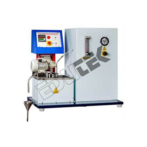 (ET-412D)
ISOTHERMAL SEMI-BATCH REACTOR APPARATUS
Price: 500 INR/Piece
Specification: ISOTHERMAL BATCH REACTOR APPARATUS Description: An isothermal semi-batch reactor is a semi-closed system with one input stream. It is operated under conditions like Isothermal (Temperature of Reaction Mass remains constant) and perfectly mixed (composition of reaction mixture is uniform throughout). This set-up is used to study a non-catalytic homogeneous reaction under isothermal condition. The set up consists of a Reactor fitted in a constant temperature water bath. Before starting the reaction, the reactor is charged with measured quantity of one reactant. From a feed tank another reactant is fed to the reactor. Using a sampling pipette samples can be taken out for analysis after fixed interval. Peristaltic Pumps are provided to measure the individual flow of Chemicals. One stirrer is fitted for mixing the reactants in reactor and other is fitted in water bath to keep the uniform temperature throughout in the bath. The temperature of bath can be maintained from ambient to 70C with the help of Digital Temperature indicator Cum Controller. Experimentation: To study a second order saponification reaction in a Semi-Batch Reactor. To determine the Reaction Rate Constant. Product Details: Voltage: 220 Volt (v) Power: 500 Watt (w) Material: Metal Usage: For Laboratory Equipment Materials: SS
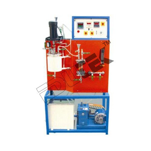 (ET-241X)
EMULSION POLYMERIZATION SET-UP APPARATUS
Price: 500 INR/Piece
Specification: EMULSION POLYMERIZATION SET-UP APPARATUS The set-up is used to carry out the emulsion polymerization involving the polymerization of an unsaturated monomer like Styrene. The emulsion is of the type: oil in water, the monomer is oil soluble & the initiator is water-soluble & an emulsifier is used to create a stable emulsion. Apparatus can be used to generate the kinetic data for emulsion polymerization under various operating conditions like temperature, emulsifier concentration, etc. Polymerization is carried out under the atmosphere of air-free nitrogen. The set-up consists of a jacketed type SS reactor fitted with a variable speed agitator & baffle. Hot water from a digitally controlled water bath is circulated in the jacket using a pump. Metered quantity of nitrogen gas from a cylinder passes through a de-oxygenation column & allowed to enter the reactor. Air has to be evacuated using a vacuum pump to create a vacuum of up to 30mm of Hg before passing the nitrogen supply. Initiator from the reservoir is supplied to the reactor under pressure. Set-up is complete & self-contained with sampling ports Experimentation/Learning Objectives: The parameter studies are conducted involving studies of Effect of RPM on conversion. Effect of Initiator concentration. Effect of monomer concentration Effect of emulsifier concentration. Utilities Required The parameter studies are conducted involving studies of Effect of RPM on conversion. Effect of Initiator concentration. Effect of monomer concentration Effect of emulsifier concentration.
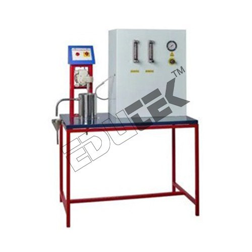 (ET-451I)
R.T.D. STUDIES IN PACKED BED REACTOR APPARATUS
Price: 500 INR/Piece
Specification: R.T.D. STUDIES IN PACKED BED REACTOR APPARATUS Axial diffusion and dispersion of fluid in packed beds are important for design and operation of separation equipment and Chemicals reactors. The tracer technique, the most widely used method for the study of axial dispersion. In stimulus response experimentation, we perturb the system using pulse input of tracer and then see how the system reacts or responds to this stimulus. The analysis of the response gives the desired information about the system. The setup consists of a glass column packed with Rasching Rings and one feed tank. Water is fed to the reactor through liquid distributor, fitted at the bottom of the column. Rotameter is provided to measure the flow of water. The flow rate can be adjusted by operating the needle valve provided on Rotameter. For understanding the R.T.D. characteristics, a special arrangement to inject tracer into the lower end of reactor, using a syringe, is provided. Samples can be taken periodically from the top outlet of reactor. Pressure Regulator & Pressure Gauge are fitted in the compressed air line. Experimentation/Learning Objectives To plot RTD curve for Packed Bed Reactor. To determine the Dispersion No. Utilities Required Compressed Air Supply: 0.25 CFM@1 bar Water Supply. Floor Drain. Floor Area Required: 1.0 m x 1.0 m. Instruments, Laboratory Glassware and Chemicals required for analysis as per the system adopted. Technical Details Reactor Column: Material Borosilicate Glass Packing: Rasching Rings, Material Borosilicate Glass. Size 8-10mm (approx.) Feed Tank: Material Stainless Steel, Capacity 20 Ltrs. Feed Circulation: By compressed air. Flow Measurement: Rotameter. Piping: Stainless Steel and PU pipe. Pressure Regulator: 0-2 Kg/cm2 Pressure Gauge: Bourdon type 0-2 Kg/cm2 Stop Watch: Electronic Arrangement is done to inject tracer into the lower end of reactor
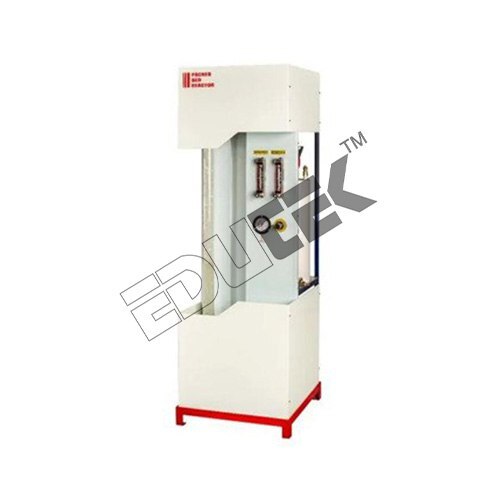 (ET-254P)
PACKED BED REACTOR APPARATUS
Price: 500 INR/Piece
Specification: PACKED BED REACTOR APPARATUS The setup consists of a glass column packed with Rasching Rings and two feed tanks. Reactants are fed to the reactor through liquid distributor, fitted at the bottom of the column. Rotameters are provided to measure the individual flow of Chemicals. The flow rate can be adjusted by operating the needle valves provided on respective Rotameter. The compressed air is used for circulation of feed. Samples can be taken periodically from the top outlet of reactor. Pressure Regulator &Pressure Gauge are fitted in the compressed air line. Product Specification Reactor Column: Material Borosilicate Glass Volume 1.2 Ltrs. (Approx.) Packing: Rasching Rings, Material Borosilicate Glass. Size 6-8 mm (approx.) Feed Tank: Material Stainless Steel, Capacity 20 Ltrs. Feed Circulation: By compressed air Flow Measurement: Rotameter 2Nos. (One each for Reactants). Piping: Stainless Steel and PU Pipe
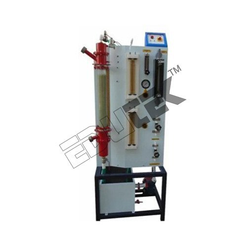 (ET-670I)
HYDRODYNAMICS OF TRICKLE BED REACTOR APPARATUS
Price: 500 INR/Piece
Specification: HYDRODYNAMICS OF TRICKLE BED REACTOR APPARATUS Description The set-up consists of a glass column. Arrangement is made for changing the glass column conveniently and filling it with any type of packing required. Air from a regulated pressure vessel passes through a sparger and allowed to enter in the column at the top. Liquid is feed from a tank, fitted with a pump and is distributed at the top of a column using a spray nozzle. Set-up is fully accompanied with manometers required. Solenoid valves are provided in the feed line at the top of column for instant release and close. The flow rate can be adjusted by operating the valves provided in respective line. Experimentation/Learning Objectives To determine Hydrodynamics of a Trickle Bed Reactor involving the measurement of pressure drop, hold-up & flow regime. Utilities Required Electricity Supply: Single Phase, 220 V AC, 50 Hz, 5-15 Amp combined socket with earth connection. Earth voltage should be less than 5 volts. Compressed Air supply@2 Bar. Water Supply Floor Area Required: 1.5 m x 0.75 m. Floor Drain. Technical Details Packed Bed: Material Borosilicate Glass Dia. 80mm, Height 600mm Packings: Glass Beads Dia. 3mm/Rasching Rings, size 8-10mm Flow measurement: By Rotameter-2Nos. (One each for water and air). Liquid Feed Tank: Material Stainless Steel, Capacity 60 Ltrs. (Approx.) Feed Circulation: Centrifugal Pump, FHP Crompton/Standard make. Air Tank: Compatible Capacity. Pressure Regulator (2 Nos.): Operating range 0-2 kg/cm2 and 0-10 kg/cm2 Pressure Gauge: Bourdon Type. Mixing Chamber: Material Stainless Steel, Compatible Capacity (For Air & Water). Liquid Catch Pot: Material Stainless Steel, Compatible Capacity. Solenoid Valve: 2Nos. (One each at Liquid and air inlet). Manometers: Compatible capacity. Piping: Material Stainless Steel and PVC/PU pipe Control Valves: Material Gun Metal/Brass
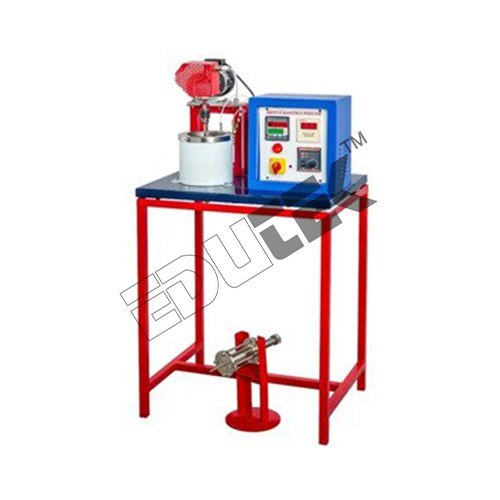 ( ET-152T)
KINETIC OF DISSOLUTION OF BENZOIC ACID APPARATUS
Price: 500 INR/Piece
Specification: KINETIC OF DISSOLUTION OF BENZOIC ACID APPARATUS Description The setup consists of a Reactor in which solid cylinder of Benzoic Acid is placed and water is stirred by means of a variable speed mixer. Baffles are also provided. The Reactor is made of Stainless Steel. A Peltilizer is provided to make the solid cylinder of size 1" diameter and 2" height of Benzoic Acid. Experimentation/Learning Objectives To study the Kinetics of dissolution of Benzoic Acid. Utilities Required Electricity Supply: Single Phase, 220 V AC, 50 Hz, 5-15 Amp combined socket with earth connection. Earth voltage should be less than 5 volts. Water Supply. Floor Drain. Floor Area Required: 1.0 m x 0.5 m. Instruments, Laboratory Glassware and Chemicals required for analysis as per the system adopted. Technical Details Chamber: Material Stainless Steel, Capacity 1 Ltrs. (approx.) Peltilizer: 1" Diameter, 2" Height (approx.). with spanner (compatible size) Stirrer: Material Stainless Steel Impeller and shaft coupled with FHP motor Control panel comprises of: Standard make on/off switch, Mains Indicator etc.
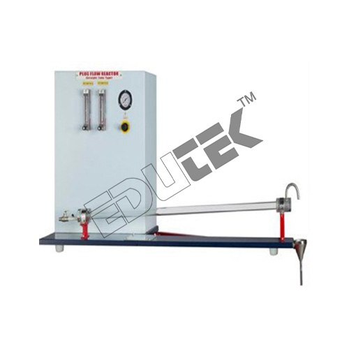 (ET-158I)
PLUG FLOW TUBULAR REACTOR (STRAIGHT TUBE TYPE) APPARATUS
Price: 500 INR/Piece
PLUG FLOW TUBULAR REACTOR (STRAIGHT TUBE TYPE) APPARATUS In an ideal Plug Flow Reactor (PFTR) there is no mixing in the direction of flow and complete mixing perpendicular to direction of flow. Concentration of reactants varies along the length of reactor but not in radial direction. This set-up is used to study a non-catalytic homogeneous reaction under ambient condition. The set up consists of two feed tanks through which two reactants are fed to the reactor. Rotameters are provided to measure the individual flow of Chemicals. The flow rate can be adjusted by operating the needle valves provided on respective Rotameter. The compressed air is used for circulation of feed. Samples are collected for analysis from the outlet of reactor. Pressure Regulator, Pressure Gauge and Safety Valve are fitted in the compressed air line. Experimentation: Saponification Reaction Study in straight tube Plug Flow Reactor. To determine Reaction Rate Constant. Specifications: Feed Tank (2Nos.): Material Stainless Steel, Capacity: 20 Ltrs. Feed Circulation: By compressed air. Flow Measurement: Rotameter 2 Nos. (One each for Reactants). Piping: Stainless Steel and PVC Pressure Gauge: Bourdon type 0-2 Kg/cm2. Stop Watch: Electronic. The whole unit is assembled rigidly on a base plate and mounted on a stand. Most of the parts are powder coated and rest are painted with auto paints. Services Required: Compressed Air Supply at 2 Bar, 0.5 CFM. Water Supply. Drain. Instruments, Laboratory Glassware and Chemicals required for analysis as per the system adopted.
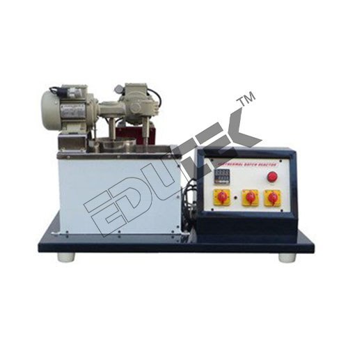 (ET-749G)
ISOTHERMAL BATCH REACTOR APPARATUS
Price: 500 INR/Piece
ISOTHERMAL BATCH REACTOR APPARATUS Description: A batch reactor is a closed system with no input and output streams. A batch reactor can operate under conditions like Isothermal (Temperature of Reaction Mass remains constant), perfectly mixed (composition of reaction mixture is uniform throughout), and constant volume (volume of the reaction mixture within the reactor remains constant, there is no appreciable change in the density of reaction mass). This set-up is used to study a non-catalytic homogeneous reaction under isothermal condition. The set up consists of a Reactor fitted in a constant temperature water bath. One stirrer is fitted for mixing the reactants in reactor and other is fitted in water bath to keep the uniform temperature throughout in the bath. The temperature of bath can be maintained from ambient to 90C with the help of Digital Temperature indicator Cum Controller. Samples can be taken out with the help of a sampling pipette. Experimentation: To study the progress of a Chemicals reaction and determine the kinetic parameters. To determine the effect of temperature on Reaction Rate Constant. Product Details: Power: 500 Watt (w) Voltage: 9 240 Volt (v) Material: Metal Usage: Laboratory Equipment Materials: SS
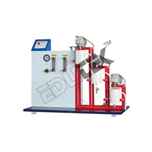 (ET-171N)
CASCADE CONTINUOUS STIRRED TANK REACTOR (CASCADE C.S.T.R.) APPARATUS
Price: 500 INR/Piece
Specification: CASCADE CONTINUOUS STIRRED TANK REACTOR (CASCADE C.S.T.R.) APPARATUS Description: In an ideal CSTR (i.e. an ideal steady state flow reactor) the contents in reactor this set-up is used to study a non-catalytic homogeneous second order liquid phase reaction under ambient condition. The setup consists of three CSTR arranged in series and two feed tanks through which two reactants are fed to the reactor. Rotameters are provided to measure the individual flow of Chemicals. The flow rate can be adjusted by operating the needle valves provided on respective Rotameter. The compressed air is used for circulation of feed. Reactants from feed tanks enter in the first CSTR and are passed to second CSTR and so on. For analysis samples are collected from different ports provided. Pressure Regulator Pressure Gauge and Safety Valve are fitted in the compressed air line. Experimentation: To study the performance of Cascade of three equal volumes CSTRs in series for the saponification of a reaction. To draw the performance chart for the reactor system and evaluate the reaction rate constant at ambient condition. Product Details: Voltage: 230 Volt (v) Material: Metal Usage: For College Labs Power: 1500 Watt (w) Equipment Materials: SS
 (ET-383W)
CONTINUOUS STIRRED TANK REACTOR (C.S.T.R.) APPARATUS
Price: 500 INR/Piece
Specification: CONTINUOUS STIRRED TANK REACTOR (C.S.T.R.) APPARATUS Provided to measure the individual flow of Chemicals. The flow rate can be adjusted by operating the needle valves provided on respective Rota meter. The compressed air is used for circulation of feed. The CSTR is fitted with stirrer for proper mixing. From top outlet of it samples are collected for analysis. Pressure Regulator, Pressure Gauge and Safety Valve are fitted in the compressed air line. Learning Objectives/Experiments: To study the progress of a suitable Chemical Reaction CSTR. To determine the Reaction Rate Constant. Required for Operation: Compressed Air Supply at 1 HP, 2 CFM. Water Supply. Drain. Electricity Supply: 1 Phase, 220 V AC, 0.5 kW. Instruments, Laboratory Glassware and Chemicals required for analysis as per the system adopted. Control Panel: Standard make on off switch, Mains Indicator etc.
 (ET-250P)
CHEMICAL REACTOR SERVICE UNIT APPARATUS
Price: 500 INR/Piece
Specification: CHEMICAL REACTOR SERVICE UNIT APPARATUS Description This set-up is designed to conduct experiments on different types of chemical reactors on the same service unit. Different types of reactors i.e. continuously Stirred Tank Reactor (CSTR), Plug Flow Tubular Reactor (Coiled Tube Type) and Batch Reactor (which will be supplied on extra cost) as separate units can be installed on the service unit individually one at a time for conducting experiments. Basically this range of small-scale chemical reactors represents the most common types of chemical reactor found in industry. The reactors use the saponification reaction between ethyl acetate and sodium hydroxide. This provides a well-understood and safe reaction for the students to investigate the different reactor types. Each reactor, mounted on a base plate can be attached to the service unit. The appropriate services such as feed circulation, instrumentation for and temperature measurement are connected to the reactor, and it then becomes operational. This service unit comprises feed tanks, rotameters for flow measurement of reactant etc. Compressed air is used for feed circulation. These all things are mounted on a compact and well-designed base for bench mounting. This is self-contained bench top service unit to accommodate the reactors, one at a time, for conducting experiments on the same unit. Utilities Required Electricity Supply: Single Phase, 220 V AC, 50 Hz, 5-15 Amp combined socket with earth connection. Earth voltage should be less than 5 volts. Compressed Air Supply: 2 CFM@1 bar Water Supply. Floor Drain. Floor Area: 2.0 m x 1.0 m Instruments, Laboratory Glassware and Chemicals required for analysis as per the system adopted. Technical Details Feed Tanks: 2Nos. (One each for each reactant) Material: Stainless Steel Capacity: 5 Ltrs. Each. Feed Circulation: By compressed air Temperature Controller: PID Controller, 0-199.9C Heater: Nichrome wire Heater. Hot water Circulator: With water tank and pump to circulate water. Temperature Sensor: RTD PT-100 Type. Piping: Stainless steel & PU pipe. Control panel comprises of: With Standard make on/off switch, Mains Indicator etc. An ENGLISH instruction manual consisting of experimental procedures, block diagram etc. will be provided along with the Apparatus. The whole set-up is well designed and arranged on a rigid structure painted with industrial PU Paint
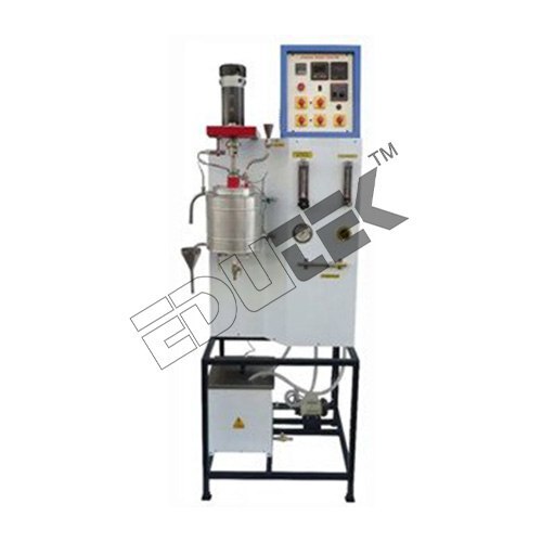 (ET-123E)
CONDENSATION POLYMERIZATION SET-UP APPARATUS
Price: 500 INR/Piece
Specification: CONDENSATION POLYMERIZATION SET-UP APPARATUS Condensation Polymerization kettle is used to carry out a condensation polymerization reaction under batch conditions. The polymerization reaction can be acid-catalyzed or self-catalyzed. The set-up can be used to measure the extent of reaction & also the reaction rate constant. The set-up consists of a jacketed type SS reactor fitted with variable speed agitator & baffles. The reactor is fitted with Nichrome wire heaters and the temperature is controlled by the digital temperature controller. Metered quantity of nitrogen gas from a cylinder, allowed entering in the reactor. Set-up is complete & self-contained with sampling ports. The top cover can be removed for cleaning purposes. Feed is fed from the top through a funnel provided with S.S. Ball Valve. An outlet is given to the Condenser fitted with a Perkin™s triangle for collecting the condensate. Vapors are allowed to enter the shell of a condenser and cooling water is allowed to pass through the tube and condensate is collected. Experimentation/Learning: Objectives to study the kinetics of Condensation Polymerization in a Batch Reactor under isothermal conditions. To calculate the rate constant and extent of reaction with and without acid catalyst. Utilities Required Electricity Supply: Single Phase, 220 VAC, 50 Hz, 5-15 Amp combined socket with earth connection. Earth voltage should be less than 5 volts. Water Supply Floor Drain. Floor Area: 1.5 m x 1.0 m Instruments, Laboratory wares, and Chemicals required for analysis as per the system adopted. High purity N2 Gas Cylinder with pressure regulator, end connection 1/4³ BSP female.
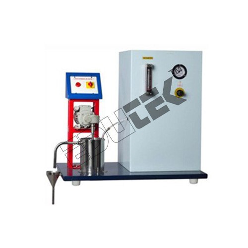 (ET-259J)
R.T.D. STUDIES IN CONTINUOUS STIRRED TANK REACTOR APPARATUS
Price: 500 INR/Piece
Specification: R.T.D. STUDIES IN CONTINUOUS STIRRED TANK REACTOR APPARATUS Description: Real reactors do not satisfy the idealized flow patterns, back mix flow or plug flow deviation from ideality can be due to channeling of fluid through the vessel, recycling of fluid within the vessel or due to the presence of stagnant region or pockets of fluid in the vessel. To predict the exact behavior of a vessel as a Chemicals reactor, RTD or stimulus response technique is used. The setup consists of one feed tank through which water is fed to the reactor. The flow rate can be varied by changing the speed of peristaltic pump. The continuously stirred tank reactor made of Stainless Steel is provided for understanding the R.T.D. characteristics. Experimentation: To plot RTD curve for a CSTR. Using pulse tracer. To determine the Dispersion No. Product Specifications Material: Metal Power: 500 Watt (w) Voltage: 220 Volt (v) Usage For: College and University Equipment Materials: SS
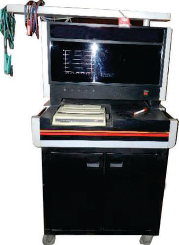
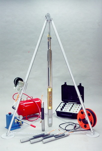
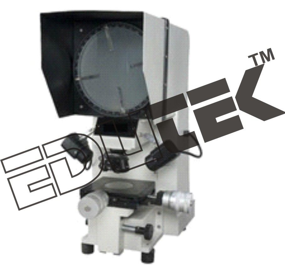
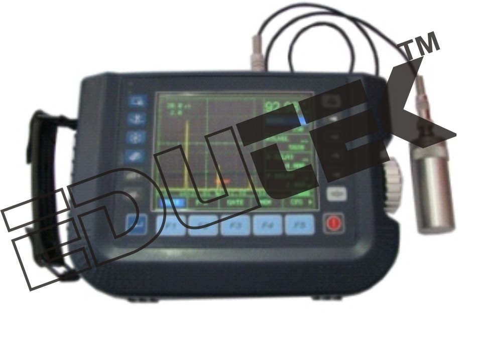
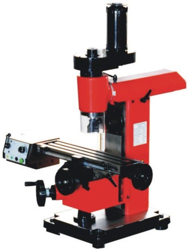
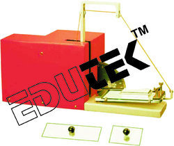
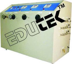
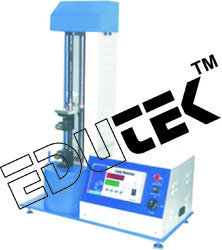
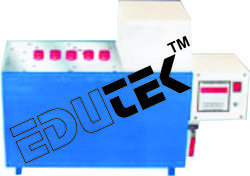
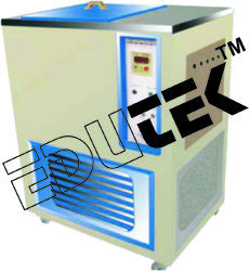
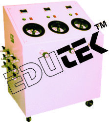
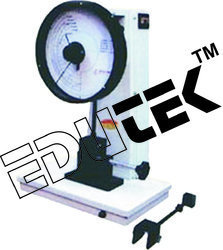
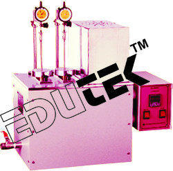
X
|
|
"We deal all over World but our main domestic market is South India"

- EDUTEK INSTRUMENTATION
GST : 06AEWPJ6896D1ZU - Factory: 70, Edutek House, Main Road Vikaspuri, Industrial Area, Ambala Cantt - 133006, Haryana, India
- Phone :07313726362

- Email Id : edutekgroup@gmail.com
- Mr Aditya Kumar (Director-International Sales)
- Mobile :07313726362
- edutekgroup@gmail.com
 |
EDUTEK INSTRUMENTATION
All Rights Reserved.(Terms of Use) Developed and Managed by Infocom Network Private Limited. |


