Demonstration of Pelton Turbine
Product Details:
X
Product Description
DEMONSTRATION OPERATING PRINCIPLE OF A PELTON TURBINE
The hydraulic turbines are turbomachines with which the hydraulic energy is used. The Pelton turbine belongs to the group of drive or stock turbines. These result in the complete transformation of the energy of water pressure into kinetic energy in the distributor. To do this, the jet of water accelerates in a nozzle and hits the blades of the Pelton wheel tangentially. In the blades the jet of water is almost deflected by almost 180 . The impulse of the water jet is transmitted to the Pelton wheel.
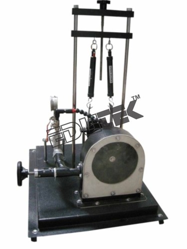
The model of a Pelton turbine, with which it demonstrates the operation of an action turbine. The test equipment consists of the Pelton wheel, a needle nozzle as a distributor, A belt brake for the turbine load and a casing with the transparent front wall. Through it you can see the flow of water, the Pelton wheel and the nozzle in operation. By adjusting the nozzle needle, the cross section of the nozzle is modified, and thus the flow rate.
The torque of the turbine is determined by measuring the force on the belt brake. To measure the number of revolutions, a counter-revolution counter is required, A pressure gauge indicates the hydraulic pressure at the turbine inlet.
The test equipment is simply and safely placed on the work surface of the basic module . The water supply and the flow measurement are also made through the. Alternatively, the test equipment can also be connected to the laboratory network.
The teaching material, well structured, represents the fundamentals and guides step by step through the different essays.
Learning Objectives / Experiments
- Design and function of a Pelton turbine
- Determination of torque, power and efficiency
- Graphical representation of characteristic curves for torque, power and efficiency
Specification:
- Function of a Pelton turbine
- Transparent front panel for observing the operating area
- Loading the turbine by use of the band brake
- Adjustable nozzle needle for setting different nozzle cross-sections
- Marking on brake drum for non-contact speed measurement
- Instruments: spring balances for determining the torque, manometer shows pressure at turbine inlet
- Flow rate determination by base module
- Water supply using base module or via laboratory supply
Technical Data:
- Pelton turbine
- Output: 5W at 500min-1, approx. 30L/min, H=2m
Pelton wheel:
- 14 blades
- Blade width: 33,5mm
- External diameter: 132mm
Needle nozzle:
- Jet diameter: 10mm
Measuring ranges:
- Braking force (spring balance): 10N
- Pressure: 0...1bar
Dimensions and Weight:
- LxWxH: 440x440x670mm
- Weight: approx. 22kg
Tell us about your requirement

Price:
Quantity
Select Unit
- 50
- 100
- 200
- 250
- 500
- 1000+
Additional detail
+91
Email
Other Products in 'Fluid Mechanics Lab Equipment' category
"We deal all over World but our main domestic market is South India"
 |
EDUTEK INSTRUMENTATION
All Rights Reserved.(Terms of Use) Developed and Managed by Infocom Network Private Limited. |


